Installation and Commissioning
8-21
7SA6 Manual
C53000-G1176-C156-2
8.1.3.3
Jumper Settings on Printed Circuit Boards
Processor Board
C-CPU-2
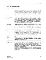
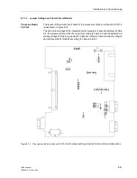
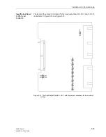
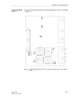
The layout of the printed circuit board of the processor printed circuit board C-CPU-2
is illustrated in Figure 8-12.
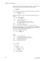
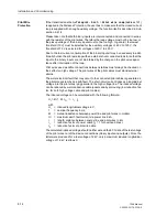
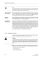
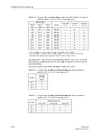
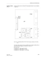
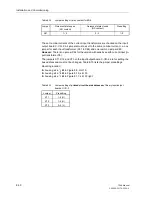
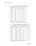
The set nominal voltage of the integrated current supply is checked according to Table
8-2, the quiescent state of the life contact according to Table 8-3 and the selected op-
erating voltage of the binary inputs BI1 to BI5 according to Table 8-4 and the integrat-
ed interface RS232 / RS485 according to Table 8-5 to 8-7.
Figure 8-12
Processor printed circuit board C-CPU-2
with jumper settings required for the module configuration
+
–
F1
X2
1
2
1
X5
1
3
1
2
X53
3
1
2
X5
2
12
34
X40
31
2
1
2
X55
3
4
X2
2
2
1
3
4
X23
2
1
3
4
X2
4
2
1
3
4
X25
2
1
3
4
X1
06
1
2
3
X1
04
1
2
3
X
105
1
2
3
X10
3
X10
9
1
2
3
X10
7
1 2 3
X111
X110
1 2 3X108
X9
0
12
3
G1
Содержание siprotec 7SA6
Страница 2: ...Siemens Aktiengesellschaft Book No C53000 G1176 C156 2 ...
Страница 18: ...xviii 7SA6 Manual C53000 G1176 C156 2 ...
Страница 32: ...Introduction 1 14 7SA6 Manual C53000 G1176 C156 2 ...
Страница 82: ...Hardware and Connections 2 50 7SA6 Manual C53000 G1176 C156 2 ...
Страница 119: ...SIPROTEC 4 Devices 4 25 7SA6 Manual C53000 G1176 C156 2 Figure 4 20 CFC Logic example ...
Страница 190: ...Configuration 5 62 7SA6 Manual C53000 G1176 C156 2 ...
Страница 559: ...Control During Operation 7 45 7SA6 Manual C53000 G1176 C156 2 Figure 7 45 Circuit breaker trip test in DIGSI 4 ...
Страница 652: ...Installation and Commissioning 8 78 7SA6 Manual C53000 G1176 C156 2 ...
Страница 724: ...Technical Data 10 56 7SA6 Manual C53000 G1176 C156 ...
Страница 800: ...Appendix A 76 7SA6 Manual C53000 G1176 C156 2 ...
Страница 866: ...Appendix B 66 7SA6 Manual C53000 G1176 C156 2 ...


