


Functions
6-61
7SA6 Manual
C53000-G1176-C156-2
When entering the relay parameters with a personal computer and DIGSI
®
4 it can be
selected whether the settings are entered as primary or secondary values.
In the case of parameterization with secondary quantities, the values derived from the
grading coordination chart must be converted to the secondary side of the current and
voltage transformers. In general the following applies:
Accordingly, the reach for any distance zone can be specified as follows:
where
N
CT
— is the transformation ratio of the current transformers
N
VT
— is the transformation ratio of the voltage transformers
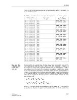
Calculation example:
110 kV overhead line 150 mm
2
with the following data:
s (length) = 35 km
R
1
/s
= 0.19
Ω
/km
X
1
/s
= 0.42
Ω
/km
R
0
/s
= 0.53
Ω
/km
X
0
/s
= 1.19
Ω
/km
Current transformers 600 A/5 A
Voltage transformers110 kV/0,1 kV
The line data is calculated with these values as follows:
R
L
= 0.19
Ω
/km · 35 km = 6.65
Ω
X
L
= 0.42
Ω
/km · 35 km = 14.70
Ω
The first zone should be set to 85 % of the line length; the result is
primary:
X1
prim
= 0.85 · X
L
= 0.85 · 14.70
Ω
= 12.49
Ω
or secondary:
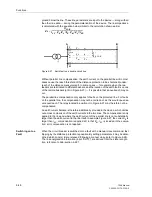
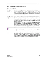
Resistance Margin
The resistance setting R allows a margin for fault resistance which appears as an ad-
ditional resistance at the fault location and is added to the impedance of the line con-
ductors. It comprises, for example, the resistance in arcs, the tower footing resistance
and others. The setting must allow for these fault resistance, but should at the same
time not be larger than necessary. On long heavily loaded lines, the setting may ex-
tend into the load impedance range. Fault detection due to overload conditions is then
prevented with the load trapezoid. Refer to the margin heading “Load Area (only for
Impedance Pick-up)” in Subsubsection 6.2.3.2. The resistance margin setting may be
separately set for the phase–phase faults on the one hand and the phase–earth faults
on the other hand. It is therefore possible to allow for a larger fault resistance for earth
faults for example.
Most important for this setting on overhead lines, is the resistance of the fault arc. In
cables on the other hand, an appreciable arc is not possible. On very short cables,
Z
secondary
Current transformer ratio
Voltage transformer ratio
-----------------------------------------------------------------------
Z
primary
⋅
=
X
sec
N
CT
N
VT
----------
X
prim
⋅
=
X1
sec
N
CT
N
VT
----------
X1
prim
⋅
600 A/5 A
110 kV/0.1 kV
--------------------------------------
12.49
Ω
⋅
1.36
Ω
=
=
=
Содержание siprotec 7SA6
Страница 2: ...Siemens Aktiengesellschaft Book No C53000 G1176 C156 2 ...
Страница 18: ...xviii 7SA6 Manual C53000 G1176 C156 2 ...
Страница 32: ...Introduction 1 14 7SA6 Manual C53000 G1176 C156 2 ...
Страница 82: ...Hardware and Connections 2 50 7SA6 Manual C53000 G1176 C156 2 ...
Страница 119: ...SIPROTEC 4 Devices 4 25 7SA6 Manual C53000 G1176 C156 2 Figure 4 20 CFC Logic example ...
Страница 190: ...Configuration 5 62 7SA6 Manual C53000 G1176 C156 2 ...
Страница 559: ...Control During Operation 7 45 7SA6 Manual C53000 G1176 C156 2 Figure 7 45 Circuit breaker trip test in DIGSI 4 ...
Страница 652: ...Installation and Commissioning 8 78 7SA6 Manual C53000 G1176 C156 2 ...
Страница 724: ...Technical Data 10 56 7SA6 Manual C53000 G1176 C156 ...
Страница 800: ...Appendix A 76 7SA6 Manual C53000 G1176 C156 2 ...
Страница 866: ...Appendix B 66 7SA6 Manual C53000 G1176 C156 2 ...


