Installation and Commissioning
8-31
7SA6 Manual
C53000-G1176-C156-2
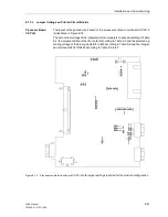
Input/Output Board
C–I/O–11
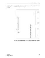
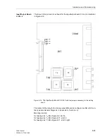
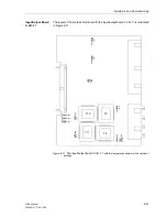
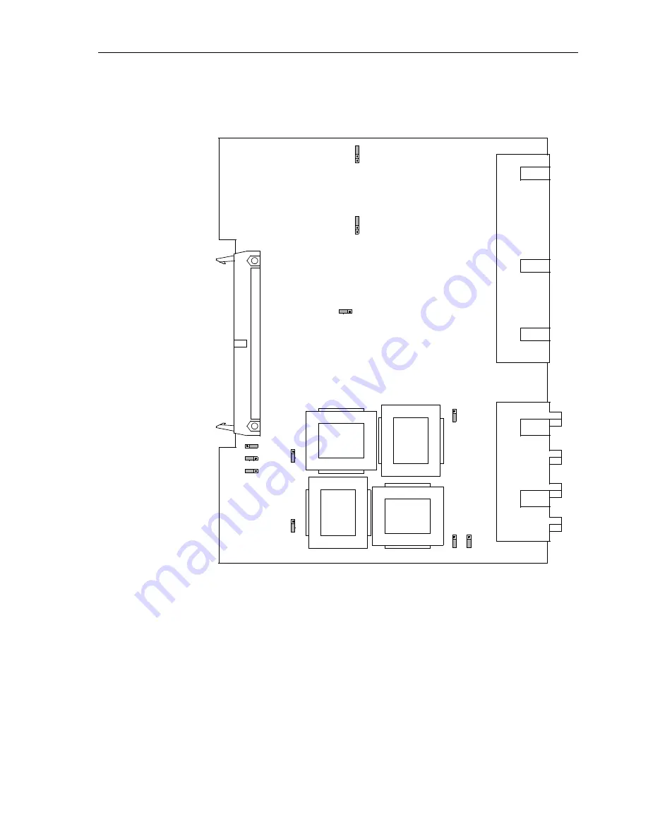
The layout of the printed circuit board for the input/output board C-I/O–11 is illustrated
in Figure 8-17.
Figure 8-17
The input/output board C-I/O–11
with the jumpers necessary for the control of
settings.
T8
T10
T11
T9
X60
(AD2)
L
X62
1A
5A
12
3
X63
1A
5A
12
3
X61
1A
5A
12
3
X64
1A
5A
12
3
X65
IE
E
IE
X73
1
2
3
(AD1)
X72
1
2
3
(AD0)
X7
1
H
1A
5A
1
2
3
X21
1
X2
2
1
LM
H
L
M
H
Содержание siprotec 7SA6
Страница 2: ...Siemens Aktiengesellschaft Book No C53000 G1176 C156 2 ...
Страница 18: ...xviii 7SA6 Manual C53000 G1176 C156 2 ...
Страница 32: ...Introduction 1 14 7SA6 Manual C53000 G1176 C156 2 ...
Страница 82: ...Hardware and Connections 2 50 7SA6 Manual C53000 G1176 C156 2 ...
Страница 119: ...SIPROTEC 4 Devices 4 25 7SA6 Manual C53000 G1176 C156 2 Figure 4 20 CFC Logic example ...
Страница 190: ...Configuration 5 62 7SA6 Manual C53000 G1176 C156 2 ...
Страница 559: ...Control During Operation 7 45 7SA6 Manual C53000 G1176 C156 2 Figure 7 45 Circuit breaker trip test in DIGSI 4 ...
Страница 652: ...Installation and Commissioning 8 78 7SA6 Manual C53000 G1176 C156 2 ...
Страница 724: ...Technical Data 10 56 7SA6 Manual C53000 G1176 C156 ...
Страница 800: ...Appendix A 76 7SA6 Manual C53000 G1176 C156 2 ...
Страница 866: ...Appendix B 66 7SA6 Manual C53000 G1176 C156 2 ...


