Functions
6-80
7SA6 Manual
C53000-G1176-C156-2
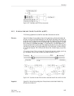
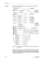
If a communication converter is used, the device and the communication converter are
linked with a FO5 module via optical fibres. The converter itself is equipped with
different interfaces for the connection to the communication network. For ordering
information see Appendix A, Subsection A.1.1, Accessories.
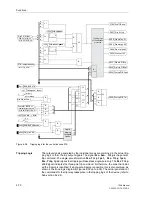
Figure 6-46
Examples for communication connections
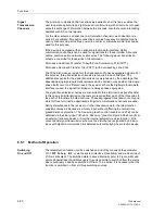
Disturbance and
Transmission Fault
The communication is continuously monitored by the devices.
Single faulty data telegrams are not a direct risk if they occur only occasionally. They
are recognized and counted in the device which detects the disturbance and can be
read out as statistical information.
If several faulty or no data telegrams are received, this is regarded as a data
disturbance
in the communication as soon as a time delay for data disturbance alarm
(default setting 100 ms, configurable) is exceeded. An alarm is output. When the
system offers no alternative way of communication (as for the ring topology), the
teleprotection scheme is disabled. As soon as the data transmission operates properly
again, the devices will automatically switch back to the teleprotection scheme.
Operating time jumps that, for example, can occur in case of switchings in the
communication network can be recognized and corrected by the device. After at least
2 seconds the operating times are measured again.
7SA6
7SA6
typical 1.5 km with
62.5/125 µm Multimode fibre
FO5 with
ST-connector
at both ends
7SA6
7SA6
typical 3.5 km with
62.5/125 µm Multimode fibrer
7SA6
7SA6
typical 10 km with
9/125 µm Monomode fibre
7SA6
7SA6
typical 35 km with
62.5/125 µm Monomode fibre
7SA6
typical 1,5 km with
62.5/125 µm Multimode fibre
7SA6
typical 1.5 km with
62.5/125 µm Multimode fibre
Communication Network
o
e
o
e
Communication
Converter
Communication
Converter
FO5 with
ST-connector
at both ends
X21 or
G703.1
X21 or
G703.1
FO6 with
ST-connector
at both ends
FO7 with
ST-connector
at both ends
FO7 with
FC-connector
at both ends
FO5 with
ST-connector
at both ends
Note:
The redundancy of different communication connections (for ring topology) requires a
consequent separation of the devices connected to the communication network. Dif-
ferent lines should not be conducted via the same multiplex-card, as there are no oth-
er lines which could be used instead when the card failed.
Содержание siprotec 7SA6
Страница 2: ...Siemens Aktiengesellschaft Book No C53000 G1176 C156 2 ...
Страница 18: ...xviii 7SA6 Manual C53000 G1176 C156 2 ...
Страница 32: ...Introduction 1 14 7SA6 Manual C53000 G1176 C156 2 ...
Страница 82: ...Hardware and Connections 2 50 7SA6 Manual C53000 G1176 C156 2 ...
Страница 119: ...SIPROTEC 4 Devices 4 25 7SA6 Manual C53000 G1176 C156 2 Figure 4 20 CFC Logic example ...
Страница 190: ...Configuration 5 62 7SA6 Manual C53000 G1176 C156 2 ...
Страница 559: ...Control During Operation 7 45 7SA6 Manual C53000 G1176 C156 2 Figure 7 45 Circuit breaker trip test in DIGSI 4 ...
Страница 652: ...Installation and Commissioning 8 78 7SA6 Manual C53000 G1176 C156 2 ...
Страница 724: ...Technical Data 10 56 7SA6 Manual C53000 G1176 C156 ...
Страница 800: ...Appendix A 76 7SA6 Manual C53000 G1176 C156 2 ...
Страница 866: ...Appendix B 66 7SA6 Manual C53000 G1176 C156 2 ...

