Functions
6-127
7SA6 Manual
C53000-G1176-C156-2
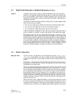
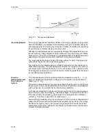
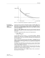
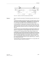
Figure 6-74
Directional characteristic using
I
Y
as polarization quantity
For the determination of direction a minimum current
I
E
and a minimum polarization
quantity is required. The minimum polarizing voltage set as
3U0>
. If the displacement
voltage is too small, the direction can only be determined if it is polarized with the
transformer star-point current and this exceeds a minimum value corresponding to the
setting
IY>
. The direction determination with U
E
is inhibited when a trip of the voltage
transformer mcb is reported via binary input.
Direction
Determination with
Negative Sequence
System
It is advantageous to use negative sequence system values for the direction measure-
ment if the resulting zero sequence voltages during earth faults are too small for an
accurate measurement or when the zero sequence values are subject to interference
by for example mutual coupling from a parallel line.
Otherwise this function operates the same as the direction measurement with zero se-
quence current and zero sequence voltage. The negative sequence signals 3
I
2
und
3U
2
are simply used instead of the signals 3
I
0
und 3U
0
. These signals must also have
a minimum magnitude of
3I2>
or
3U2>
.
Blocking
The earth fault protection can be blocked by the distance protection. If in this case a
fault is detected by the distance protection, the earth fault protection will not operate.
This gives the selective fault clearance by the distance protection preference over trip-
ping by the earth fault protection.
The earth fault protection can also be blocked during the single-pole dead time of an
automatic reclose cycle. This prevents an incorrect measurement resulting from the
zero sequence current and voltage signals arising in this state. If the device is com-
bined with an external automatic reclose device or if single-pole tripping can result
from a separate (parallel tripping) protection device, the earth fault protection must be
blocked via binary input during the single-pole open condition.
Switching onto an
Earth Fault
To achieve fast tripping following manual closure of the circuit breaker on to an earth
fault, the manual close command from the control switch can be routed to the device
via a binary input. The earth fault protection can then trip three-pole without delay. The
stage(s) that should be activated for instantaneous tripping after manual closure can
be selected with setting parameters. (refer to logic diagrams Figure 6-69 to 6-71).
Im
U
E
= 3U
0
„Forward“
„Reverse“
α
β
Re
I
E
k
Y
e
j76°
I
Y
β
= 122°
α
= –22°
U
P
Содержание siprotec 7SA6
Страница 2: ...Siemens Aktiengesellschaft Book No C53000 G1176 C156 2 ...
Страница 18: ...xviii 7SA6 Manual C53000 G1176 C156 2 ...
Страница 32: ...Introduction 1 14 7SA6 Manual C53000 G1176 C156 2 ...
Страница 82: ...Hardware and Connections 2 50 7SA6 Manual C53000 G1176 C156 2 ...
Страница 119: ...SIPROTEC 4 Devices 4 25 7SA6 Manual C53000 G1176 C156 2 Figure 4 20 CFC Logic example ...
Страница 190: ...Configuration 5 62 7SA6 Manual C53000 G1176 C156 2 ...
Страница 559: ...Control During Operation 7 45 7SA6 Manual C53000 G1176 C156 2 Figure 7 45 Circuit breaker trip test in DIGSI 4 ...
Страница 652: ...Installation and Commissioning 8 78 7SA6 Manual C53000 G1176 C156 2 ...
Страница 724: ...Technical Data 10 56 7SA6 Manual C53000 G1176 C156 ...
Страница 800: ...Appendix A 76 7SA6 Manual C53000 G1176 C156 2 ...
Страница 866: ...Appendix B 66 7SA6 Manual C53000 G1176 C156 2 ...


