Installation and Commissioning
8-10
7SA6 Manual
C53000-G1176-C156-2
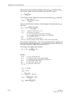
In case a power transformer is situated between the feeder VT set and the busbar VTs
the phase shift according to the vector group of the transformer must be considered
for the synchronism check function if this is used. In this case, check also the relevant
addresses
212
Usync connect.
,
214
ϕ
Usync-Uline
, and
215
U-line /
Usync
. Respective notes and an example are given in Subsection 6.1.1 under “Volt-
age Transformer Connection”.
Binary Inputs and
Outputs
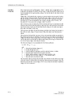
The configuration of the binary in and outputs, i.e. the individual adaptation to the plant
conditions, is described in Section 5.2. The connections to the plant are dependent on
this actual configuration. The presettings of the device are listed in Appendix A, Sec-
tion A.4. Check also if the labelling corresponds to the allocated message functions.
Changing Setting
Groups with Binary
Inputs
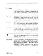
If binary inputs are used to switch setting groups, note:
•
Two binary inputs must be dedicated to the purpose of changing setting groups
when four groups are to be switched. One binary input must be set for “
>Set
Group Bit 0
”, the other input for “
>Set Group Bit 1
”. If either of these input
functions is not assigned, then it is considered as not controlled.
•
To control two setting groups, one binary input set for “
>Set Group Bit 0
” is
sufficient since the binary input “
>Set Group Bit 1
”, which is not assigned, is
considered to be not controlled.
•
The status of the signals controlling the binary inputs to activate a particular setting
group must remain constant as long as that particular group is to remain active.
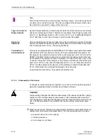
Table 8-1 shows the relationship between “
>Set Group Bit 0
”, “
>Set Group Bit
1
”, and the setting groups A to D. Principal connection diagrams for the two binary in-
puts are illustrated in Figure 8-7. The figure illustrates an example in which both Set
Group Bits 0 and 1 are configured to be controlled (actuated) when the associated bi-
nary input is energized (high).
no
= not energized
yes
= energized
Table 8-1
Setting group selection with binary inputs — example
Binary Input Events
Active Group
>Set Group Bit 0 >Set Group Bit 1
no
no
Group A
yes
no
Group B
no
yes
Group C
yes
yes
Group D
Содержание siprotec 7SA6
Страница 2: ...Siemens Aktiengesellschaft Book No C53000 G1176 C156 2 ...
Страница 18: ...xviii 7SA6 Manual C53000 G1176 C156 2 ...
Страница 32: ...Introduction 1 14 7SA6 Manual C53000 G1176 C156 2 ...
Страница 82: ...Hardware and Connections 2 50 7SA6 Manual C53000 G1176 C156 2 ...
Страница 119: ...SIPROTEC 4 Devices 4 25 7SA6 Manual C53000 G1176 C156 2 Figure 4 20 CFC Logic example ...
Страница 190: ...Configuration 5 62 7SA6 Manual C53000 G1176 C156 2 ...
Страница 559: ...Control During Operation 7 45 7SA6 Manual C53000 G1176 C156 2 Figure 7 45 Circuit breaker trip test in DIGSI 4 ...
Страница 652: ...Installation and Commissioning 8 78 7SA6 Manual C53000 G1176 C156 2 ...
Страница 724: ...Technical Data 10 56 7SA6 Manual C53000 G1176 C156 ...
Страница 800: ...Appendix A 76 7SA6 Manual C53000 G1176 C156 2 ...
Страница 866: ...Appendix B 66 7SA6 Manual C53000 G1176 C156 2 ...

