Index
Index-6
7SA6 Manual
C53000-G1176-C156
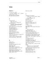
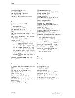
Phase Segregated Fault Detection
6-296
Phase segregated initiation
6-253
Phase–Earth Loops
6-43
Phase–Phase Loops
6-42
Pick-up
6-178, 10-33
Pickup and Assignment
to the Polygons
6-59
Pick-up Mode
6-34
Pickup Scheme
6-37
Pickup Schemes
6-34
Pilot Wire Comparison
6-109
Plug-in Connectors
A-11
Polarity Check
8-64
Polarity of Current Transformers
6-7
Pole discrepancy supervision
6-262
Power
Plant Connections
8-44
Power Supply
10-2
Power supply
1-4
Power Supply Voltage
8-15
Power Swing Blocking
6-76
Power Swing Supplement
1-9, 10-18
Power Swing Tripping
6-76
Power System Data 1
6-7
Presettings
A-66
Primary or Secondary Values
6-6
Processing of the circuit breaker auxiliary
contacts
6-250
Processing of the Circuit Breaker Position
6-293
Processing the circuit breaker auxiliary contacts
6-192
Processor Printed Circuit Boards C-CPU-2
8-21
PROFIBUS DP
4-31
PROFIBUS FMS
4-31
Protection and Control
4-2
Protection data interface
10-29
Protection Data Interfaces and Protection Data
Topology (optional)
6-78
Protection Functions
1-5
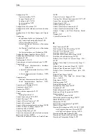
Purpose of Setting Groups
6-14
Purpose of Signal Transmission
6-89
Q
Quantities
8-59
R
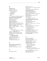
Rack Mounting and Cubicle Mounting
8-4
Rated Frequency
6-10
Rating of the Protected Plant
6-17
Read and Set Date and Time
7-28
Reading out Metered Values
7-21
Read-out of Information
Fault Records
7-26
Messages
7-2
Switching Statistics
7-13
Read-out of Measured Values
7-15
Real Time Clock and Buffer Battery
10-46
Rear Service / Modem Interface
10-6
Reassembling the Device
9-14
Reassembly of Device
8-40
Reclose Block
6-191
Reduced dead time (RDT)
6-196
Remote measured values
7-17
Remote Trip of the Circuit Breaker at the
Opposite Line End
6-160
Replacing the Buffer Battery
9-4
Replacing the Power Supply Fuse
9-13
Representation of the Time
7-29
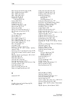
Reset of the Trip Command
6-299
Resetting and Setting the Switching Statistics
7-14
Resetting of Metered Values and Minimum/
Maximum Values
7-24
Resistance Margin
6-61
Response to Failures
6-283
Restoring Factory Settings
6-15
Retrieval
Device configurations
5-35
Interface settings
5-56
ordering number
3-4
Retrieved messages
7-7
Return
9-16
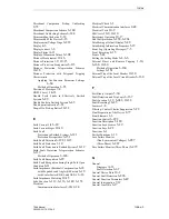
Reverse Interlocking
6-111
Routine Checks
9-3
Routine Checks and Maintenance
9-1
RS 485 Termination
8-42
Run-Time Properties
5-39
S
Sammelmeldungen
6-286
Sampling Frequency
6-275
Saving and Erasing the Messages
7-11
Saving the Fault Records
7-27
Scope of Functions
1-9
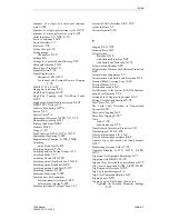
Screw Terminal Connections
2-11, 2-29, 2-38
Selectivity before Reclosure
6-189
Sensitive Earth Fault Directional Determination
6-181
Separate Operator Control Element
10-55
Содержание siprotec 7SA6
Страница 2: ...Siemens Aktiengesellschaft Book No C53000 G1176 C156 2 ...
Страница 18: ...xviii 7SA6 Manual C53000 G1176 C156 2 ...
Страница 32: ...Introduction 1 14 7SA6 Manual C53000 G1176 C156 2 ...
Страница 82: ...Hardware and Connections 2 50 7SA6 Manual C53000 G1176 C156 2 ...
Страница 119: ...SIPROTEC 4 Devices 4 25 7SA6 Manual C53000 G1176 C156 2 Figure 4 20 CFC Logic example ...
Страница 190: ...Configuration 5 62 7SA6 Manual C53000 G1176 C156 2 ...
Страница 559: ...Control During Operation 7 45 7SA6 Manual C53000 G1176 C156 2 Figure 7 45 Circuit breaker trip test in DIGSI 4 ...
Страница 652: ...Installation and Commissioning 8 78 7SA6 Manual C53000 G1176 C156 2 ...
Страница 724: ...Technical Data 10 56 7SA6 Manual C53000 G1176 C156 ...
Страница 800: ...Appendix A 76 7SA6 Manual C53000 G1176 C156 2 ...
Страница 866: ...Appendix B 66 7SA6 Manual C53000 G1176 C156 2 ...

