


Functions
6-320
7SA6 Manual
C53000-G1176-C156-2
Monitoring the
Command Execu-
tion
−
Interruption of a command because of a cancel command
−
Running time monitor (feedback message monitoring time)
6.24.3 Interlocking
Interlocking is executed by the user-defined logic (CFC). The interlocking checks of a
SICAM/SIPROTEC
®
-system are classified into:
•
System interlocking checked by a central control system (for a busbar)
•
Zone controlled/bay interlocking checked in the bay device (for the feeder)
System interlocking relies on the system data base in the central control system. Zone
controlled/bay interlocking relies on the status of the circuit breaker and other switches
that are connected to the relay.
The extent of the interlocking checks is determined by the configuration and interlock-
ing logic of the relay.
Switchgear which is subject to system interlocking in the central control system is
marked with a parameter (in the routing matrix)
For all commands the user can select the operation mode with interlocking (normal
mode) or without interlocking (test mode):
−
for local commands by reprogramming the settings with password check,
−
for automatic commands via command processing with CFC mittels Entriegelung-
skennungen,
−
for local / remote commands, using an additional interlocking disable command, via
Profibus.
6.24.3.1 Interlocked/Non-Interlocked Switching
The command checks that can be selected for the SIPROTEC
®
-relays are also re-
ferred to as “standard interlocking”. These checks can be activated (interlocked) or de-
activated (non interlocked) via DIGSI
®
4.
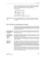
Deactivated interlock switching means the configured interlocking conditions are not
checked in the relay.
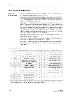
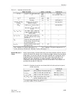
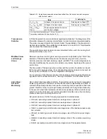
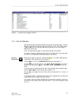
Interlocked switching means that all configured interlocking conditions are checked in
the command check. If a condition could not be fulfilled, the command will be rejected
by a message with a minus added to it (e.g. “CO
-
”), immediately followed by an oper-
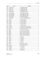
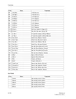
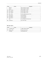
ation response information. Table 6-20 shows some types of commands and messag-
Содержание siprotec 7SA6
Страница 2: ...Siemens Aktiengesellschaft Book No C53000 G1176 C156 2 ...
Страница 18: ...xviii 7SA6 Manual C53000 G1176 C156 2 ...
Страница 32: ...Introduction 1 14 7SA6 Manual C53000 G1176 C156 2 ...
Страница 82: ...Hardware and Connections 2 50 7SA6 Manual C53000 G1176 C156 2 ...
Страница 119: ...SIPROTEC 4 Devices 4 25 7SA6 Manual C53000 G1176 C156 2 Figure 4 20 CFC Logic example ...
Страница 190: ...Configuration 5 62 7SA6 Manual C53000 G1176 C156 2 ...
Страница 559: ...Control During Operation 7 45 7SA6 Manual C53000 G1176 C156 2 Figure 7 45 Circuit breaker trip test in DIGSI 4 ...
Страница 652: ...Installation and Commissioning 8 78 7SA6 Manual C53000 G1176 C156 2 ...
Страница 724: ...Technical Data 10 56 7SA6 Manual C53000 G1176 C156 ...
Страница 800: ...Appendix A 76 7SA6 Manual C53000 G1176 C156 2 ...
Страница 866: ...Appendix B 66 7SA6 Manual C53000 G1176 C156 2 ...


