Trinity SS180 TMA 9182 Скачать руководство пользователя страница 1

SS180 TMA

®

(Model 9182)

.

Product Description

Assembly Manual

Revision B June 2013

Part No. 115359B

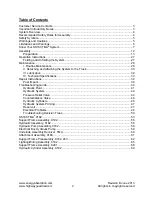
Содержание SS180 TMA 9182

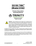
Страница 1: ...SS180 TMA Model 9182 Product Description Assembly Manual Revision B June 2013 Part No 115359B...

Страница 2: ...ccepted by the Federal Highway Administration for use on the national highway system under strict criteria utilized by that agency Energy Absorption Systems representatives are available for consultat...

Страница 3: ...g the System to the Truck 30 III Lubrication 32 IV Technical Specifications 33 Repair Instructions 34 Post Impact 34 Troubleshooting Guide 40 Hydraulic Fluid 41 Hydraulic System 42 Pressure Relief Val...

Страница 4: ...ly in conjunction with the assembly of the SS180 TMA system and are for standard assemblies only as specified by the applicable highway authority In the event your system assembly requires or involves...

Страница 5: ...ork area Warning Ensure that all of the SS180 TMA system Warnings Cautions and Important Statements within the SS180 TMA Manual are completely followed Failure to follow this warning could result in s...

Страница 6: ...protect all personnel while at the assembly maintenance or repair site Failure to follow this warning could result in serious injury or death in the event of a collision Warning Use only Energy Absorp...

Страница 7: ...d injury to person s or property Impacts that exceed the specifications of the system may not result in acceptable crash performance as outlined in NCHRP Report 350 relative to structural adequacy occ...

Страница 8: ...the truck on the curb side See Figure 2 When tilting the TMA care shall be taken to stay clear of all moving parts Figure 1 Figure 2 STAND HERE FOR CONTROLS ON RIGHT SIDE OF TRUCK CONTROLS CAN BE ON...

Страница 9: ...pport frame See Figure 3 3 Make sure all pivot pins are in position and that all retaining pins are assembled correctly See Figure 4 Figure 4 The SS180 TMA shall be deployed in the unfolded position A...

Страница 10: ...operating the system The operator should never stand under the TMA when it is raised or attempting to lower it 6 Folding the TMA provides the best maneuverability and driving characteristics It is adv...

Страница 11: ...The TMA shall not be used for any other purpose 12 Regular maintenance of the TMA is critical for proper operation Refer to the maintenance section of this Manual for additional information Regular i...

Страница 12: ...TMA See the assembly section for further details Definitions The BARRIER VEHICLE is the truck on which a TMA is mounted while positioned upstream towards the direction that traffic is approaching of a...

Страница 13: ...Assemble Necessary tools Recommended Tools Welding equipment for 1 2 plate GMAW or SMAW Cutting torch Hammer Drift pin or alignment pin 12 long Tape measure 1 2 drive socket wrench w 6 extension 1 2...

Страница 14: ...ly sized truck that requires no ballast should be used Because the 943 kg 2080 lbs weight of the rearward protruding TMA is supported by the back of the shadow vehicle care must be taken not to exceed...

Страница 15: ...Page 15 Position the Socket Receiver at the rear end of the frame so that the 76 x 387 mm 3 x 15 1 4 flat bar is along the outside of the frame member and the Socket Receiver Assembly is flush with th...

Страница 16: ...vision B June 2013 www highwayguardrail com 15 All rights in copyright reserved Note Left and right Underride Socket Receivers must be parallel with each other and level Figure 11 Socket Hitch Left Si...

Страница 17: ...them into place using the 1 x 6 1 4 Hitch Pins and Retainer Pins shipped with the system Figure 12 7 Mount the Support Brackets to Socket Receivers Mount the Support Brackets to the Socket Hitches as...

Страница 18: ...Frame Backup to the Attachment Assembly Move the system to the truck and pin the Support Frame Backup Assembly to the Support Brackets See Figure 14 The system is to be assembled while the Support Fr...

Страница 19: ...reserved 9 Extend the Support Frame With the TMA pinned to Attachment Assembly slowly and evenly pull the frame out to its full extent Warning Even when supported by forklift frame can be unwieldy Us...

Страница 20: ...rt Frame is fully extended Assemble the Bottom Release Cable across Arm Assemblies See Figure 16 Torque the nuts to 34 3 N m 25 2 ft Ib 300 24 in lb making sure that roughly an equal amount of threads...

Страница 21: ...shers and nuts provided Torque the nuts to 120 7 N m 90 5 ft lb 1080 30 in lb Repeat procedure for Cartridge A See Figure 17 12 Assemble the Top Release Cables across the Arm Assemblies Verify that th...

Страница 22: ...place using the second nut as a jam nut 14 Assemble and Tension the Cartridge Support Cables There are six Cartridge Support Cables Assemble the cables as shown in Figure 19 Attach thimble end of all...

Страница 23: ...Levelness of the System Frame Verify that the system frame is 305 25 mm 12 1 from the ground at the front and rear of the system It may be necessary to add shims to the Socket Hitch in order to adjus...

Страница 24: ...volt versions Be sure the system and truck are compatible Be sure to use standard safety practices when attaching the battery cables e g do not let the ends of the cables touch etc Do not run the batt...

Страница 25: ...I ATF fluid if it is not Do not overfill Replace the vent plug in the filler port Be careful not to cross thread it Read Operation Instructions See Page 27 Folding and Unfolding the System Making sure...

Страница 26: ...Arm Assemblies and stored when TMA is in service 20 Check System Lights for Proper Operation Verify that all the turn stop tail reverse lights are working properly Replace any bulbs that are out Ther...

Страница 27: ...sure they will not be damaged during folding and unfolding of the system 22 Final Check of System Check the tightness of all of the fasteners Double check the height and levelness of the system 23 Re...

Страница 28: ...nd behind the system is clear of all objects before proceeding Under no circumstances shall anyone be allowed behind the system when it is being folded or unfolded When operating from the cab always b...

Страница 29: ...teners Be sure to check bolts attaching the cartridges to the support structure Lock washers shall be fully compressed 1 month 3 Cables System unfolded A Cartridge Support Cables The spring length sha...

Страница 30: ...move all residue or debris on or around the pump 1 month 9 Hydraulic Rams Clean the Hydraulic Rams Remove all residue or debris on or around the rams 1 month 10 Hydraulic Hoses Check all Hydraulic Hos...

Страница 31: ...rted Figure 24 D Unplug the light harness and disconnect the positive and negative cables from the pump Unplug the Cab Switch Box at the mating connector on the TMA E Remove the Socket Hitches from th...

Страница 32: ...g the assembly difficult it may be necessary to adjust Jacks or temporarily uncouple the Socket Hitches from the TMA Be sure the retainer pins are inserted correctly and cannot fall out C Plug in the...

Страница 33: ...ith water Use only Dexron III ATF fluid The empty oil capacity of the reservoir hoses and cylinders is approximately 4 quarts the capacity of the reservoir alone is approximately 2 1 2 quarts The rese...

Страница 34: ...igure 30 Figure 31 Figure 32 3 Replacement Parts For details on replacement parts refer to the drawing package The drawings include the part numbers and descriptions For replacement parts contact cust...

Страница 35: ...ure that the system collapses properly Refer to the system drawings for the part numbers and descriptions of the parts 2 Inspect pins and bolts for damage Replace all bolts and pins that have been dam...

Страница 36: ...om Release Cable across the Arm Assemblies Verify that the frame is fully extended Attach the Bottom Release Cable across Arm Assemblies See Figure 33 Torque the nuts to 34 N m 0 3 25ft Ibf 0 2 making...

Страница 37: ...n and secure it using the flat washers lock washers and nuts provided Torque the nuts to 120 7 N m 90 5 ft lb Repeat procedure for Cartridge A See Figure 34 7 Assemble the Top Release Cables across th...

Страница 38: ...that the diagonal measurements in each bay are the same A B 5 mm 3 16 C D 5 mm 3 16 Lock each cable in place using the second nut as a jam nut 9 Replace Side Guides The Side Guides must be inspected a...

Страница 39: ...idge Support Cables tighten the first nut on one cable until all slack is removed then tighten it until the tensioning springs have been compressed to 32 mm 1 1 4 in height Lock this nut in place with...

Страница 40: ...re working properly Replace any bulbs that are out There are two light circuits on the TMA Verify both circuits are operational Raise the system to folded position and verify secondary lights are work...

Страница 41: ...of a voltage in the electrical circuit With the alligator clip grounded the light glows when the probe comes into contact with a hot electrical component 3 Continuity Light A continuity light is like...

Страница 42: ...II has been found to be the best readily available fluid for the job in most climate conditions 2 Selecting Fluids for Applications Outside ATF S Temperature Range When looking for fluids that can be...

Страница 43: ...at pump Electrical system inoperative Verify that cable from battery is correctly attached Failed motor solenoid Replace taking note of correct wire locations for reassembly 2 System Operates Rough or...

Страница 44: ...p Overheats Low voltage at pump Check battery and wiring Incorrect low volume or dirty oil Add or change oil as necessary Excessive internal leakage pump Replace the pump contact Energy Absorption Sys...

Страница 45: ...nergy Absorption Systems Customer Service Department to purchase replacement parts Warning Do not exceed pressure rating for hydraulic system components System pressure is set to 2400 psi at the facto...

Страница 46: ...a Again make sure the system is completely folded or completely unfolded b Remove the Cartridge from the valve body being cautious of oil spray from residual pressure in the system c Clean the Cartrid...

Страница 47: ...o not disconnect the Follower Link Pivot and the Push Link Pivot where they are bolted to the Weldment Front Intermediate Frame and the Weldment Rear Intermediate Frame respectively D At the top end o...

Страница 48: ...ged a few times to work out any air in the system Add oil at the filler port any time that the pump begins to cavitate E Jog the system a few times by depressing FOLD or UNFOLD depending on the curren...

Страница 49: ...system failure A Signs that point to low voltage are 1 Motor won t run because solenoid won t shift 2 Motor running at reduced speed B Minimum voltage requirements 1 Between the motor stud and ground...

Страница 50: ...ent section 3 Use a circuit test light to test the switch See Test Equipment section B Motor solenoid switches The solenoid switches found on the hydraulic pump are four post style solenoid They shall...

Страница 51: ...www energyabsorption com Revision B June 2013 www highwayguardrail com 50 All rights in copyright reserved Troubleshooting Decision Trees...

Страница 52: ...www energyabsorption com Revision B June 2013 www highwayguardrail com 51 All rights in copyright reserved...

Страница 53: ...www energyabsorption com Revision B June 2013 www highwayguardrail com 52 All rights in copyright reserved...

Страница 54: ...www energyabsorption com Revision B June 2013 www highwayguardrail com 53 All rights in copyright reserved SS180 TMA 9182 DWG 9182 Sheet 1 of 2...

Страница 55: ...www energyabsorption com Revision B June 2013 www highwayguardrail com 54 All rights in copyright reserved DWG 9182 Sheet 2 of 2...

Страница 56: ...www energyabsorption com Revision B June 2013 www highwayguardrail com 55 All rights in copyright reserved DWG 3526820 0000 Support Frame Assembly 9182...

Страница 57: ...www energyabsorption com Revision B June 2013 www highwayguardrail com 56 All rights in copyright reserved DWG 3526806 Sheet 1 of 2 Hydraulic Assembly 9182...

Страница 58: ...www energyabsorption com Revision B June 2013 www highwayguardrail com 57 All rights in copyright reserved DWG 3526806 Sheet 2 of 2...

Страница 59: ...www energyabsorption com Revision B June 2013 www highwayguardrail com 58 All rights in copyright reserved Hydraulic Pump Assembly 9182 DWG 3526807...

Страница 60: ...www energyabsorption com Revision B June 2013 www highwayguardrail com 59 All rights in copyright reserved Electrical Box Hydraulic Pump DWG 3526808...

Страница 61: ...www energyabsorption com Revision B June 2013 www highwayguardrail com 60 All rights in copyright reserved Underride Assembly Receiver TMA DWG 616797...

Страница 62: ...www energyabsorption com Revision B June 2013 www highwayguardrail com 61 All rights in copyright reserved Attachment Assembly 9180 DWG 604382...

Страница 63: ...www energyabsorption com Revision B June 2013 www highwayguardrail com 62 All rights in copyright reserved Support Frame Preassembly 9182 24V DWG 352682A Sheet 1 of 3...

Страница 64: ...www energyabsorption com Revision B June 2013 www highwayguardrail com 63 All rights in copyright reserved DWG 352682A Sheet 2 of 3...

Страница 65: ...www energyabsorption com Revision B June 2013 www highwayguardrail com 64 All rights in copyright reserved DWG 352682A Sheet 3 of 3...

Страница 66: ...www energyabsorption com Revision B June 2013 www highwayguardrail com 65 All rights in copyright reserved Lighting Wiring Assembly 9182 DWG 3526800 Sheet 1 of 3...

Страница 67: ...www energyabsorption com Revision B June 2013 www highwayguardrail com 66 All rights in copyright reserved DWG 3526800 Sheet 2 of 3...

Страница 68: ...www energyabsorption com Revision B June 2013 www highwayguardrail com 67 All rights in copyright reserved DWG 3526800 Sheet 3 of 3...

Страница 69: ...www energyabsorption com Revision B June 2013 www highwayguardrail com 68 All rights in copyright reserved Support Frame Assembly 8291 DWG 3526820 0000...

Страница 70: ...www energyabsorption com Revision B June 2013 www highwayguardrail com 69 All rights in copyright reserved DWG 610306 Hydraulic Cylinder Assembly 9182...

Страница 71: ...www energyabsorption com Revision B June 2013 www highwayguardrail com 70 All rights in copyright reserved Notes...

Страница 72: ...2525 Stemmons Freeway Dallas Texas 75207 888 323 6374 USA only 214 589 8140 Outside USA www energyabsorption com www highwayguardrail com...

Отзывы: