Functions
6-230
7SA6 Manual
C53000-G1176-C156-2
been signalled via the binary input “
>FAIL:Feeder VT
” (internal signal “internal
blocking”).
The stages of the zero sequence voltage protection are automatically blocked (with
the internal automatic reclosure function) during single-pole automatic reclose dead
time to avoid pick-up with the false zero sequence values arising during this state. If
the device operates with an external automatic reclosure function or if single-pole trip-
ping can be triggered by a different protection system (operating in parallel), the over-
voltage protection for the zero sequence system must be blocked via a binary input
during single-pole tripping.
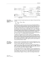
According to Figure 6-116 the device calculates the voltage to be monitored:
3
⋅
U
0
= U
L1
+ U
L2
+ U
L3
.
This applies if no suitable voltage is connected to the fourth measuring input U
4
.
However, if the displacement voltage U
en
of the voltage transformer set is directly con-
nected to the fourth measuring input U
4
of the device and this information was entered
during configuration the device will automatically use this voltage and calculate the tri-
ple zero sequence voltage.
3
⋅
U
0
=
Uph / Udelta
⋅
U
4
.
As the voltage transformation of the voltage transformer set is usually
the factor is
Uph / Udelta
= 3/
√
3 =
√
3
≈
1.73
. For more details see Power System
Data 1 in Section 6.1.1, margin heading “Voltage Transformer Connection”, address
0211
.
Figure 6-116 Logic diagram of the overvoltage protection for zero sequence voltage
Freely Selectable
Single–phase
Voltage
As the zero sequence voltage stages operate separately and independent from the
other protective overvoltage functions they can be used for any other single–phase
voltage. Therefore the fourth voltage input U
4
of the device must be assigned accord-
ingly. (also see Section 6.1.1 in “Voltage Transformer Connection”).
The same features apply as for the use of the zero sequence voltage protection, i.e.
blocking via a binary input “>
3U0>(>) BLK
”, when the asymmetrical “Fuse–Failure–
Monitor” picks up during trip of the mcb for the voltage transformers, and during the
single-pole dead time before automatic reclosure.
U
Nprim
3
------------------
U
Nsek
3
----------------
U
Nsek
3
----------------
⁄
⁄
U
L3-E
U
L2-E
U
L1-E
U>
3722
3U0>
T
0
3723
T 3U0>
T 3U0> TimeOut
3U0> Pickup
U>>
3729
3U0>(>) RESET
T
0
3725
T 3U0>>
T 3U0>> TimeOut
3U0>> Pickup
3U0>(>) TRIP
≥
1
3724
3U0>>
>3U0>(>) BLK
3U
0
U
Ph–E
FNo 10203
FNo 10270
FNo 10272
FNo 10274
FNo 10273
FNo 10271
≥
1
internal blocking
Содержание siprotec 7SA6
Страница 2: ...Siemens Aktiengesellschaft Book No C53000 G1176 C156 2 ...
Страница 18: ...xviii 7SA6 Manual C53000 G1176 C156 2 ...
Страница 32: ...Introduction 1 14 7SA6 Manual C53000 G1176 C156 2 ...
Страница 82: ...Hardware and Connections 2 50 7SA6 Manual C53000 G1176 C156 2 ...
Страница 119: ...SIPROTEC 4 Devices 4 25 7SA6 Manual C53000 G1176 C156 2 Figure 4 20 CFC Logic example ...
Страница 190: ...Configuration 5 62 7SA6 Manual C53000 G1176 C156 2 ...
Страница 559: ...Control During Operation 7 45 7SA6 Manual C53000 G1176 C156 2 Figure 7 45 Circuit breaker trip test in DIGSI 4 ...
Страница 652: ...Installation and Commissioning 8 78 7SA6 Manual C53000 G1176 C156 2 ...
Страница 724: ...Technical Data 10 56 7SA6 Manual C53000 G1176 C156 ...
Страница 800: ...Appendix A 76 7SA6 Manual C53000 G1176 C156 2 ...
Страница 866: ...Appendix B 66 7SA6 Manual C53000 G1176 C156 2 ...

