Functions
6-166
7SA6 Manual
C53000-G1176-C156-2
Stub Protection
A further overcurrent stage is the stub protection. It can however also be used as a
normal additional definite time overcurrent stage, as it functions independent of the
other stages.
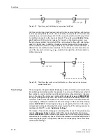
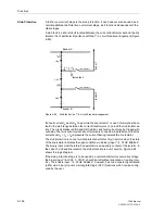
A stub fault is a short-circuit located between the current transformer set and the line
isolator. It is of particular importance with the 1
1
/
2
–circuit breaker arrangement (Figure
6-93).
Figure 6-93
Stub fault at an 1
1
/
2
–circuit breaker arrangement
If a fault current
I
A
and/or
I
B
flows while the line isolator 1 is open, this implies that a
fault in the stub range between the current transformers
I
A
,
I
B
, and the line isolator ex-
ists. The circuit breakers CBA and CBC which carry fault current may be tripped with-
out delay.The two sets of current transformers are connected in parallel such that the
current sum
I
F
=
I
A
+
I
B
represents the current flowing towards the line isolator.
The stub protection is an overcurrent protection which is only in service when the state
of the line isolator indicates the open condition via a binary input “
>I-STUB ENABLE
”.
The binary input must therefore be operated via an auxiliary contact of the isolator. In
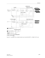
the case of a closed line isolator, the stub protection is out of service. Figure 6-94
shows the logic diagram.
If the stub protection stage is to be used as a normal definite time overcurrent stage,
the binary input “
>BLOCK I-STUB
”, should be left without allocation or routing (ma-
trix). The enable input “
>I-STUB ENABLE
”, however, has to be constantly activated
(either via a binary input or via integrated logic (CFC) functions which can be config-
ured by the user.
Busbar A
busbar B
fe
ed
er
1
fe
ede
r
2
stub fault
I
A
I
B
I
F
=
I
A
+
I
B
line isolator 1
line isolator 2
CBA
CBB
CBC
Содержание siprotec 7SA6
Страница 2: ...Siemens Aktiengesellschaft Book No C53000 G1176 C156 2 ...
Страница 18: ...xviii 7SA6 Manual C53000 G1176 C156 2 ...
Страница 32: ...Introduction 1 14 7SA6 Manual C53000 G1176 C156 2 ...
Страница 82: ...Hardware and Connections 2 50 7SA6 Manual C53000 G1176 C156 2 ...
Страница 119: ...SIPROTEC 4 Devices 4 25 7SA6 Manual C53000 G1176 C156 2 Figure 4 20 CFC Logic example ...
Страница 190: ...Configuration 5 62 7SA6 Manual C53000 G1176 C156 2 ...
Страница 559: ...Control During Operation 7 45 7SA6 Manual C53000 G1176 C156 2 Figure 7 45 Circuit breaker trip test in DIGSI 4 ...
Страница 652: ...Installation and Commissioning 8 78 7SA6 Manual C53000 G1176 C156 2 ...
Страница 724: ...Technical Data 10 56 7SA6 Manual C53000 G1176 C156 ...
Страница 800: ...Appendix A 76 7SA6 Manual C53000 G1176 C156 2 ...
Страница 866: ...Appendix B 66 7SA6 Manual C53000 G1176 C156 2 ...

