Functions
6-235
7SA6 Manual
C53000-G1176-C156-2
Negative Sequence
System Overvolt-
age U
2
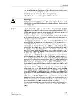
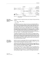
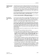
The negative sequence system voltage stages detect asymmetrical voltages. If such
voltages shall cause tripping, set the address
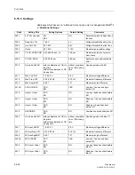
3741
U2>(>)
to
On
. If these states shall
be signalled only, set the address
U2>(>)
to
Alarm Only
, in any other cases to
Off
.
This protective function also has in two stages, one being
U2>
(address
3742
) with a
greater time delay
T U2>
(address
3743
) for stationary asymmetrical voltages and
the other being
U2>>
(address
3744
) with a short delay time
T U2>>
(address
3745
)
for high asymmetrical voltages.
Note that the negative sequence system is established according to its defining equa-
tion U
2
=
1
/
3
⋅
|U
L1
+ a
2
⋅
U
L2
+ a
⋅
U
L3
|. For symmetrical voltages and two exchanged
phases this is equivalent to the phase–to–earth voltage value.
The drop-off to pick-up ratio
U2>(>) RESET
) can be set in address
3749
. This setting
can only be modified with DIGSI
®
4 under “Additional Settings”.
Zero Sequence
System Overvolt-
age
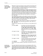
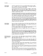
The zero sequence voltage stage can be switched
On
or
Off
in address
3721
. In ad-
dition, this stage can also be selected to
Alarm Only
i.e. these stages operate and
issue alarms only. This protection function can be used for any other single-phase
voltage which is connected to the fourth voltage measurement input U
4
. (Also refer to
Section 6.1.1 and see margin heading “Voltage Transformer Connection”).
The settings of the voltage threshold and the timer values depend on the type of ap-
plication. Here no general guidelines can be established. Generally, with a sensitive
setting of
3U0>
(address
3722
), i.e. close to operational values that are to be expect-
ed, not only the time delay
T 3U0
(address
3724
) must be greater, but also the reset
ratio
3U0 Reset Ratio
(address
3723
) must also be as large as possible. Usually
the presetting is sufficient. This setting can only be modified with DIGSI
®
4 under “Ad-
ditional Settings
”.
Similar considerations apply if this voltage stage is used for a different voltage at the
measuring input U
4
.
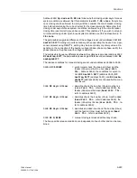
When setting the voltage values please observe the following:
•
If the U
en
-
voltage of the set of voltage transformers is connected to U
4
and if this
was already set in the power system data 1 (refer also to Section 6.1.1 under mar-
gin heading “Voltage Transformer Connection”, U4 transformer =
Udelta
transf.
), the device multiplies this voltage by the matching ratio
Uph / Udelta
(address
211
), usually with 1.73. Therefore the voltage measured is
√
3 · U
en
=
3 . U
0
.
When the voltage triangle is fully displaced, the voltage will be
√
3-times the
phase-to-phase voltage.
•
If any other voltage is connected to U
4
, which is not used for voltage protection, and
if this was already set in the power system data 1 (refer also to Section 6.1.1, “Volt-
age Transformer Connection”, e. g.
U4 transformer
=
Not connected
or
U4
transformer
=
Usync transf.
), the device calculates the zero sequence volt-
age according to its definition: 3 · U
0
= IU
L1
+ U
L2
+ U
L3
I. When the voltage triangle
is fully displaced, the voltage will be
√
3-times the phase-to-phase voltage.
•
If any other voltage is connected to U
4
, which is used for voltage protection, and if
this was already set in the power system data 1 (refer also to Section 6.1.1, “Voltage
Transformer Connection”, i. e.
U4 transformer
=
Ux transformer
), this volt-
age will be used for the voltage stages without any further factors. This “zero se-
quence voltage protection” then is, in reality, a single-phase voltage protection for
any kind of voltage at U
4
.
Содержание siprotec 7SA6
Страница 2: ...Siemens Aktiengesellschaft Book No C53000 G1176 C156 2 ...
Страница 18: ...xviii 7SA6 Manual C53000 G1176 C156 2 ...
Страница 32: ...Introduction 1 14 7SA6 Manual C53000 G1176 C156 2 ...
Страница 82: ...Hardware and Connections 2 50 7SA6 Manual C53000 G1176 C156 2 ...
Страница 119: ...SIPROTEC 4 Devices 4 25 7SA6 Manual C53000 G1176 C156 2 Figure 4 20 CFC Logic example ...
Страница 190: ...Configuration 5 62 7SA6 Manual C53000 G1176 C156 2 ...
Страница 559: ...Control During Operation 7 45 7SA6 Manual C53000 G1176 C156 2 Figure 7 45 Circuit breaker trip test in DIGSI 4 ...
Страница 652: ...Installation and Commissioning 8 78 7SA6 Manual C53000 G1176 C156 2 ...
Страница 724: ...Technical Data 10 56 7SA6 Manual C53000 G1176 C156 ...
Страница 800: ...Appendix A 76 7SA6 Manual C53000 G1176 C156 2 ...
Страница 866: ...Appendix B 66 7SA6 Manual C53000 G1176 C156 2 ...

