Functions
6-35
7SA6 Manual
C53000-G1176-C156-2
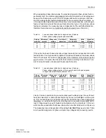
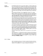
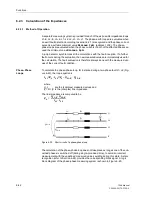
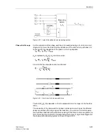
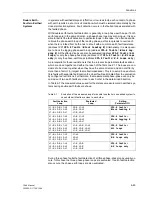
When evaluating phase–phase loops, the sensitivity towards phase–phase faults is
particularly high. In extensive compensated networks this selection is advantageous
because it excludes pick-up as a result of single earth faults on principle. With two-
and three-phase faults it automatically adapts to the prevailing infeed conditions, i.e.
in the weak-infeed operation mode it becomes more current-sensitive, with strong in-
feed and high load currents the pick-up threshold will be higher. If only phase–phase
faults are evaluated, the measuring loop is independent of the earth-fault detection,
therefore this procedure is not suitable for earthed networks (see Table 6-4).
If the option has been chosen whereby voltage loop selection is dependent on earth-
fault detection, then high sensitivity applies to phase-earth faults and to phase–phase
faults. On principle, this option is independent of the treatment of the network neutral
point, however, it requires that the earth–fault criteria according to Section 6.2.1 are
met for all earth faults or double earth faults (see Table 6-5).
Finally, it is also possible to only evaluate phase-earth voltage loops if an earth fault
has been detected. For phase–phase faults only the overcurrent
Iph>>
will then pick
up. This is advantageous in networks with neutral points that have been earthed low–
resistance, i.e. using earth-fault current limiting means (so-called “semi–solid” earth-
ing). In these cases only earth faults shall be detected by the U/I pick-up. In this net-
work it is often undesirable that phase–phase short-circuits shall result in a U/I pick-up.
The measuring loop is independent of the setting
1ph FAULTS
(address
1630A
)
. Table
6-6 shows the assignment of phase currents, loop voltages and measuring results.
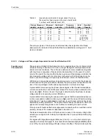
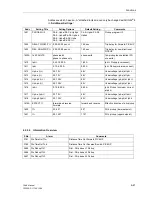
Table 6-4
Loop and phase indication for single–phase U/I pick-up;
Phase–phase voltage program (address
1601
)
Pick-up
module
Measured
current
Measured
voltage
Earth fault
detection
Parameter
1Ph FAULTS.
Valid
loop
Signalled
Phase(s)
L1
L2
L3
L1
L2
L3
L1–L2
L2–L3
L3–L1
any
any
L1–L2
L2–L3
L3–L1
L1, L2
L2, L3
L1, L3
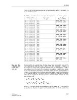
Table 6-5
Loop and phase indication for single–phase U/I pick-up;
Phase–phase voltage program in the event of earth faults, phase–phase
voltages without earth faults (address
1601
)
Pick-up
module
Measured
current
Measured
voltage
Earth–fault
detection
Parameter
1Ph ANR.
Valid
loop
Signalled
Phase(s)
L1
L2
L3
L1
L2
L3
L1–L2
L2–L3
L3–L1
no
no
no
any
L1–L2
L2–L3
L3–L1
L1, L2
L2, L3
L1, L3
L1
L2
L3
L1
L2
L3
L1–E
L2–E
L3–E
yes
yes
yes
any
L1–E
L2–E
L3–E
L1, E
L2, E
L3, E
Содержание siprotec 7SA6
Страница 2: ...Siemens Aktiengesellschaft Book No C53000 G1176 C156 2 ...
Страница 18: ...xviii 7SA6 Manual C53000 G1176 C156 2 ...
Страница 32: ...Introduction 1 14 7SA6 Manual C53000 G1176 C156 2 ...
Страница 82: ...Hardware and Connections 2 50 7SA6 Manual C53000 G1176 C156 2 ...
Страница 119: ...SIPROTEC 4 Devices 4 25 7SA6 Manual C53000 G1176 C156 2 Figure 4 20 CFC Logic example ...
Страница 190: ...Configuration 5 62 7SA6 Manual C53000 G1176 C156 2 ...
Страница 559: ...Control During Operation 7 45 7SA6 Manual C53000 G1176 C156 2 Figure 7 45 Circuit breaker trip test in DIGSI 4 ...
Страница 652: ...Installation and Commissioning 8 78 7SA6 Manual C53000 G1176 C156 2 ...
Страница 724: ...Technical Data 10 56 7SA6 Manual C53000 G1176 C156 ...
Страница 800: ...Appendix A 76 7SA6 Manual C53000 G1176 C156 2 ...
Страница 866: ...Appendix B 66 7SA6 Manual C53000 G1176 C156 2 ...


