Functions
6-184
7SA6 Manual
C53000-G1176-C156-2
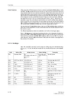
Voltage Settings
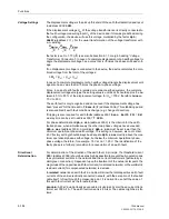
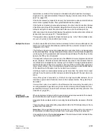
The displacement voltage is the pickup threshold of the earth fault detection and is set
in address
3002
3U0>
.
If the displacement voltage U
en
of the voltage transformer set is directly connected to
the fourth voltage measuring input U
4
of the device and if this was predefined during
the configuration, the device will use this voltage, multiplied by the factor
Uph /
Udelta
(address
211
). For the usual transformation of the voltage transformer with
e–n–winding
the factor is set to 1,73 (
√
3) (see also Subsection 6.1.1, margin heading “Voltage
Transformer Connection”). In case of a complete displacement of a healthy voltage tri-
angle the displacement voltage has a value that is
√
3 times the phase-to-phase volt-
age.
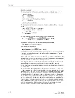
If no displacement voltage is connected to the device, the device calculates the mon-
itored voltage from the total of the voltages:
3
⋅
U
0
= |U
L1
+ U
L2
+ U
L3
|.
In case of a complete displacement of a healthy voltage triangle the displacement volt-
age also has a value that is
√
3 times the phase-to-phase voltage.
Since, in case of earth faults in isolated or resonant-earthed systems, the complete
displacement voltage emerges, the setting value is uncritical; it should approx. be be-
tween 40 % to 50 % of the displacement voltage: for U
N
= 100 V therefore between
70 V to 90 V.
The earth fault is only recognized and announced if the displacement voltage has
been “present” for the time set in
T Sens.E/F
(address
3006
). This stabilizing period
is also enabled if earth fault conditions change (e.g. change of direction).
If tripping is also required for earth faults (address
3001
,
Sens. Earth Flt
=
ON
),
a delay time can be set in address
3007
T 3U0>.
For phase determination
Uph-e min
(address
3003
) is the criterion for the earth-
faulted phase, when simultaneously the other two phase voltages have exceeded
Uph-e max
(address
3004
). Accordingly,
Uph-e min
must be set lower than the
minimum operational phase-earth voltage. This setting is, however, also not critical,
40 V (factory setting) should always be adequate.
Uph-e max
must lie above the max-
imum operational phase-earth voltage, but below the minimum operational phase-
phase voltage, therefore, for example, 75 V at U
N
= 100 V. The identification of the
faulty phase is a further precondition for annunciation of an earth fault.
Directional
Determination
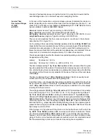
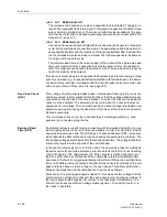
For determination of the direction of the earth fault, in principle, the threshold current
3I0>
(address
3005
) should be set as high as possible to prevent faulty operation due
to asymmetrical currents in the network and the current transformers (particularly in
Holmgreen connection). Dependent upon the treatment of the network star point, the
magnitude of the capacitive earth fault current (for isolated networks) or the wattmetric
residual current (for compensated networks) is decisive.
In isolated networks an earth fault in a cable will allow the total capacitive earth fault
currents of the entire electrically connected network, with the exception of the faulted
cable itself, to flow through the measuring point. It is normal to use half the value of
this earth fault current as the threshold value.
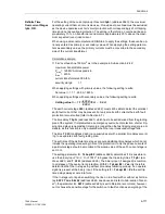
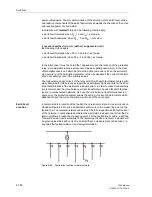
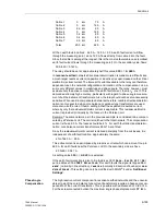
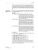
Example: A 25 kV bus-bar feeds seven cable circuits. Each circuit has a current trans-
former set 300 A/1 A. The earth fault current is 2.5 A/km. The cables might be as fol-
lows:
U
Nprim
3
------------------
U
Nsec
3
----------------
U
Nsec
3
----------------
⁄
⁄
Содержание siprotec 7SA6
Страница 2: ...Siemens Aktiengesellschaft Book No C53000 G1176 C156 2 ...
Страница 18: ...xviii 7SA6 Manual C53000 G1176 C156 2 ...
Страница 32: ...Introduction 1 14 7SA6 Manual C53000 G1176 C156 2 ...
Страница 82: ...Hardware and Connections 2 50 7SA6 Manual C53000 G1176 C156 2 ...
Страница 119: ...SIPROTEC 4 Devices 4 25 7SA6 Manual C53000 G1176 C156 2 Figure 4 20 CFC Logic example ...
Страница 190: ...Configuration 5 62 7SA6 Manual C53000 G1176 C156 2 ...
Страница 559: ...Control During Operation 7 45 7SA6 Manual C53000 G1176 C156 2 Figure 7 45 Circuit breaker trip test in DIGSI 4 ...
Страница 652: ...Installation and Commissioning 8 78 7SA6 Manual C53000 G1176 C156 2 ...
Страница 724: ...Technical Data 10 56 7SA6 Manual C53000 G1176 C156 ...
Страница 800: ...Appendix A 76 7SA6 Manual C53000 G1176 C156 2 ...
Страница 866: ...Appendix B 66 7SA6 Manual C53000 G1176 C156 2 ...

