Functions
6-172
7SA6 Manual
C53000-G1176-C156-2
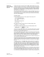
line onto a fault usually causes a large fault current. It is important to avoid that the
selected stage picks up in a transient way when energizing the line.
Inverse Time
Overcurrent Stages
IP, 3I0P
with IEC
In the case of the inverse time overcurrent stages, various characteristics can be se-
lected, depending on the version of the device and the configuration (Section 5.1, ad-
dress
126
). For the IEC–curves (address
126
Back-Up O/C
=
TOC IEC
) the follow-
ing are available in address
2660
IEC Curve
:
Inverse
(normal inverse, Type A according to IEC 60255–3),
Very inverse
(very inverse, Type B according to IEC 60255–3),
Extremely inverse
(extremely inverse, Type C according to IEC 60255–3), and
LongTimeInverse
(longtime, Type B according to IEC 60255–3).
The curves and equations that the curves are based on, are shown in the technical
data (Section 10.5, Figure 10-1).
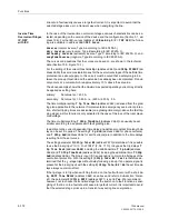
For the setting of the current thresholds
Ip>
(address
2640
) and
3I0p PICKUP
(ad-
dress
2650
) the same considerations as for the overcurrent stages of the definite time
protection (see above) apply. In this case it must be noted that a safety margin be-
tween the pick-up threshold and the set value has already been incorporated. Pick-up
only occurs at a current which is approximately 10 % above the set value.
The above example shows that the maximum expected operating current may directly
be applied as setting here:
primary:
Set value Ip> = 630 A,
secondary: Set value Ip> = 5.25 A, i.e. (630 A / 600 A) · 5 A.
The time multiplier setting
T Ip Time Dial
(address
2642
) is derived from the grad-
ing plan applicable to the network. If implemented as emergency overcurrent protec-
tion, shorter tripping times are advisable (one grading time margin above the fast trip-
ping stage), as this function is only activated in the case of the loss of the local meas-
ured voltage.
The time multiplier setting
T 3I0p TimeDial
(address
2652
) can usually be set
smaller according to a separate earth fault grading plan.
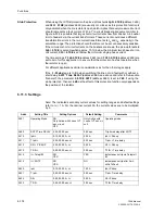
In addition to the current dependant time delay an additional constant time length de-
lay can be set if required. The setting
T Ip Add
(address
2646
for phase currents)
and
T 3I0p Add
(address
2656
for earth currents) are in addition to the time delays
resulting from the set curves.
The setting parameter
I(3I0)p Tele/BI
(address
2670
) determines if it is possible
to use the binary input “
>O/C InstTRIP
” (F.No.
7110
) to bypass the trip delays
T
Ip Time Dial
(address
2642
) including the additional time
T Ip Add
(address
2646
) and
T 3I0p TimeDial
(address
2652
) including the additional time
T 3I0p
Add
(address
2656
). The binary input (if it is assigned) is common to all stages of the
overcurrent protection. With the setting
I(3I0)p Tele/BI
=
Yes
it is therefore de-
termined that the I
P
–stage trips without delay following pick-up if an operate signal is
present at the binary input; with the setting
I(3I0)p Tele/BI
=
No
the set time de-
lays always come into effect.
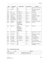
If the Ip-stage is to trip when switching the line on to a fault without or with a short de-
lay,
SOTF Time DELAY
(address
2680
, see above and refer to Sub-section “Gener-
al”), the parameter
I(3I0)p SOTF
(address
2671
) is set to Yes. We recommend,
however, not to choose the sensitive stage for the switch on to fault function as ener-
gizing of the line on to a fault should cause a large fault current. It is important to avoid
that the selected stage picks up in a transient way during line energization.
Содержание siprotec 7SA6
Страница 2: ...Siemens Aktiengesellschaft Book No C53000 G1176 C156 2 ...
Страница 18: ...xviii 7SA6 Manual C53000 G1176 C156 2 ...
Страница 32: ...Introduction 1 14 7SA6 Manual C53000 G1176 C156 2 ...
Страница 82: ...Hardware and Connections 2 50 7SA6 Manual C53000 G1176 C156 2 ...
Страница 119: ...SIPROTEC 4 Devices 4 25 7SA6 Manual C53000 G1176 C156 2 Figure 4 20 CFC Logic example ...
Страница 190: ...Configuration 5 62 7SA6 Manual C53000 G1176 C156 2 ...
Страница 559: ...Control During Operation 7 45 7SA6 Manual C53000 G1176 C156 2 Figure 7 45 Circuit breaker trip test in DIGSI 4 ...
Страница 652: ...Installation and Commissioning 8 78 7SA6 Manual C53000 G1176 C156 2 ...
Страница 724: ...Technical Data 10 56 7SA6 Manual C53000 G1176 C156 ...
Страница 800: ...Appendix A 76 7SA6 Manual C53000 G1176 C156 2 ...
Страница 866: ...Appendix B 66 7SA6 Manual C53000 G1176 C156 2 ...


