Rev: 10/10/22
Website
Max-Air Technology, Inc. • 114 Resource Drive • Wentzville, MO 63385 • United States of America
Tel +1.636.272.4934 • Toll Free 888.842.9998 • Fax 636.272.4937 • www.maxairtech.com • [email protected]
1
Fi
le
Na
m
e:
M
ax
-A
ir_
IO
M
_ME
_G
03
5~
04
4_
LV
H
V_
M
od
_c
on
ve
rt
ed.
ME G 035~044 Series LV/HV | Mod
Installation, Operation and Maintenance Instructions
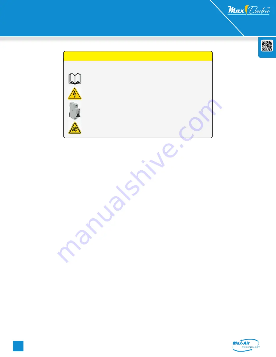
Throughout the installation phases and operation of this equipment,
safety procedures take precedence over all other activities. As a minimum:
1. Read and follow all instructions in this IOM.
2. Risk of electric shock! All wiring must be in accordance with applicable local
codes, regulations and the NEC. Be aware that there may be hazardous voltages
present which can shock, burn, or possibly cause permanent injury or even death.
3. Before handling electrical connections, disconnect power feeds. There may
be multiple power feeds connected to this unit. Check all terminal connections
carefully when servicing the actuator.
4. This is a mechanical gear train system with high torque outputs. Connected
mechanical linkages can and will cause personal injury if the user encounters a
pinch-point during movement.
Safety First!
Handling & Storage:
1. This device is an electrically powered mechanical transmission
system. It is comprised of a DC motor, an asynchronous AC motor,
or a polyphase AC motor, logic control PC boards, various discrete
electronic components and electrical storage devices, all of which
are susceptible to damage from high humidity environments. For this
reason, this device must be protected from direct contact with water
and/or high humidity storage environments.
2. Protect the device from physical damage while awaiting the
completion of installation processes.
3. If this product is installed in water valve systems and remains
unpowered during construction phases, condensate will accumulate
and possibly damage the product. This product MUST be powered up
at all times once it is installed in active piping systems.
Installation:
1. Confirm correct voltage and control before wiring and powering up
this actuator.
2. This device has been permanently lubricated at time of assembly.
Maintain proper lubrication level by ensuring the actuator is mounted
with the top cover at or above horizontal. This device is NOT designed
to mount with the top cover below horizontal.
3. Use approved conduit entry components to protect the interior of
the unit from ingress of foreign materials (including water). Utilize drip
loops to prevent conduit condensate from accumulating and entering
the actuator throught the EMT port(s).
4. Refer to the dimensional diagram (rear pages) for proper clearance
on all sides as well as the top cover clearance requirements. Determine
proper access space for the manual override system.
5. When mounting this device to a valve or damper, ensure the mating
between the valve stem (or coupling) is NOT deeper than the socket
depth in the bottom of the actuator. Use the proper length and thread
bolts for mounting. (See dimensional diagram).
6. Ensure the actuator is concentrically mounted to the valve stem.
Non-concentricity causes premature actuator or valve-stem seal
failure, or actuator stalling due to high-torque during travel.
7. Use properly sized power supplies and wire gauge over distance to
prevent actuator failure from stalling and overheating.
8. Refer to the wiring diagram sheet (folded, inserted under the
actuator cover) for wiring connections. You can also scan the QR code
above and navigate to the Max-Air website to obtain a full-size wiring
diagram.
9. Do NOT parallel wire multiple on-off actuators to the same field
control terminals. This WILL cause unexpected movement of the
actuator(s), overheating and premature failure.
10. After installation and testing, do NOT operate the actuator with any
covers removed.
11. It is recommended to operate the actuator for at least ten minutes
once per month, as a minimum.
12. The internal heater is to be used in ALL applications.
13. Mechanical travel stops are factory calibrated for 90 degree operation.
These stops are NOT designed to adjust mechanical rotation by more
than +/- 3 degrees.
14. Mechanical stops CANNOT be used to limit travel electrically. Stalling
this unit will damage the drive motor and control PCB's.


