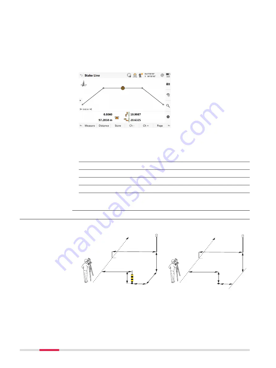
3D viewer for Stake shows information about the measured point relative to
the design. The design is defined by the selected layer and line, and the values
entered on the
General
page.
3D viewer for Check and Stake are similar. Stake contains the Stake view, along
with 2D/3D view, cross section view and navigation view.
For Check and when only a DTM job is used, 3D viewer shows the DTM and the
lines of selected Road layer - always in plan view.
At the top, DTM height and delta height are shown.
☞
Refer to "Stake,pageCheck panel,page" for a description of the icons.
For Stake, extra information is shown at the bottom:
1.
Difference in chainage is shown with some footsteps
2.
Horizontal offset is shown with some footsteps
3.
Height difference is shown as an arrow
4.
Current height
5.
The element to stake is shown as an orange and green dot
6.
The plot can be shown as profile view, plan view, orbital view and
navigation view.
45.3.2
Measuring Points by Chainage and Offset
Stake road
Check road
a
e
i
h
d
g
b
c
f
Road_034
a
e
h
g
d
b
c
f
Road_080
Stake/Check panel,
3D viewer
Graphical overview
760
Roads - Road
Содержание Captivate
Страница 1: ...Leica Captivate Technical Reference Manual Version 3 0 English...
Страница 153: ...3 Continue as if creating a new polyline Refer to Create new polyline Several segments Creating Points and Lines 153...
Страница 561: ...Next step Store saves the new coordinate system QuickGrid 561...
Страница 786: ...7 Stake Line To stake out the selected intersection point all delta values must be 0 000 786 Roads Road...
Страница 812: ...Tunnel Profile Editor Profile details view Tunnel Profile Editor Layer details view 812 Roads Tunnel...
Страница 839: ...Field Option Description Offset limit Editable field Maximum horizontal offset from defined pro file Roads Tunnel 839...
Страница 848: ...Field Option Description Scans com pleted Display only Number of scans being measured Number of total scans 848 Scanning...


