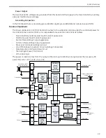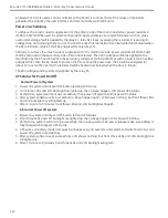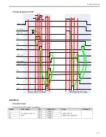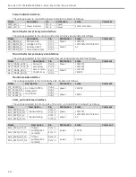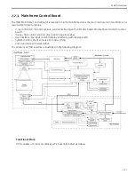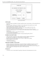
System Overview
2-19
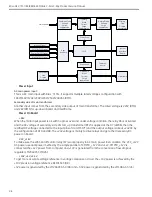
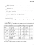
Optical coupling
-
Optical coupling circuit is responsible for changing voltage level and isolating the ground of circuit at
each sides of optical coupler.
DAC
-
DAC (Digital Analog Converter) circuit is responsible for output analog signal, such as KV setting, mA
setting and mA pre-heat.
VFC
-
VFC (Voltage Frequency Converter) circuit is responsible for converting mA signal to frequency value
in order to implement mAs function.
Communication
-
RS422 protocol is used for MCU to communicate with workstation or DAP.
-
SPI protocol is used for MCU to communicate with Control Panel.
Indication
-
Indication circuit includes LED and buzzer, which are controlled by MCU and peripheral controller.
Miscellaneous hardware
-
Other circuits include power supply, supervisor circuit, watchdog circuit, clock generator, and security
control, etc.
Power Distribution
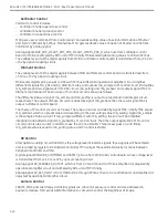
Power Supply Overview
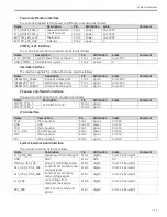
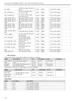
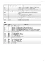
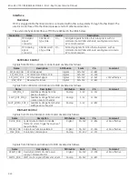
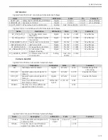
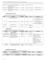
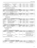
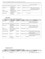
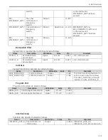
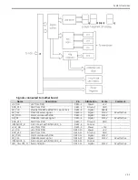
The power of MCB is drove by power supply 1 & 2 via mother board, and +3.3V, +2.5V & +1.2V are generated
from +5V_PS1. Power supplies are listed as follows.
Name
Description
Source
Scale
Pin
Comment
+5V_PS1
+5V power supply
PS1
+5V
J2-A5/B5/C5
-
GND_+5V
Reference of +5V_PS1
PS1
0V
J2-A4/B4/C4
-
-15V_PS1
-15V power supply
PS1
-15V
J2-A15/A16
-
+15V_PS1
+15V power supply
PS1
+15V
J2-C15/C16
-
AGND
Reference of -15V_PS1 & +15V_PS1
PS1
0V
J2-A9/B9/C9
-
+24V_PS1
+24V power supply
PS1
+24V
J1-B9
-
GND_+24V_PS1
Reference of +24V_PS2
PS1
0V
J1-B10
-
+15V_PS1_D
+15V power supply
PS1
+15V
J1-A29/B29/C29
-
GND_+15V_PS1_D Reference of +15V_PS1_D
PS1
0V
J1-A12/B12/C12
-
-15V_PS1_D
-15V power supply
PS1
-15V
J1-C32
-
GND_-15V_PS1_D Reference of -15V_PS1_D
PS1
0V
J1-A32
-
+24V_PS2
+24V power supply
PS2
+24V
J1-A1/B1/C1
-
GND_+24V_PS2
Reference of +24V_PS2
PS2
0V
J1-A6/B6/C6
-
+12V_PS2
+12V power supply
PS2
+12V
J1-B5
-
GND_+12V_PS2
Reference of +12V_PS2
PS2
0V
J1-A5
-
+3.3V
Internal power
+5V_PS1
+3.3V
-
By LM1084
+2.5V
Internal power
+5V_PS1
+2.5V
-
By LM1084
+1.2V
Internal power
+5V_PS1
+1.2V
-
By LM1084
Grounding Connection
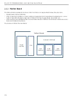
All the grounds of power are connected by mother board with one point strategy.
Содержание Brivo OEC 715
Страница 2: ......
Страница 19: ...Chapter1 Introduction and Safety...
Страница 41: ...Introduction and Safety 23 46 54 20 18 26...
Страница 55: ...Chapter2 System Overview...
Страница 137: ...Chapter3 Installation...
Страница 147: ...Installation 3 11 7 Put the ramp in position Release all bracket and move the workstation along the ramp off the pallet...
Страница 211: ...Installation 3 75 3 9 Reporting For U S Systems Complete and submit Form 2579 within 15 days of installation...
Страница 212: ...Chapter4 Calibration...
Страница 223: ...Brivo OEC 715 785 865 Mobile C Arm X Ray Product Service Manual 4 12 Mainframe Control Board TP7...
Страница 231: ...Brivo OEC 715 785 865 Mobile C Arm X Ray Product Service Manual 4 20 Mainframe Control Board TP17 POT4 J5 TP7 POT7 POT5...
Страница 275: ...Brivo OEC 715 785 865 Mobile C Arm X Ray Product Service Manual 4 64...
Страница 284: ...Chapter5 Software...
Страница 312: ...Software 5 29 4 Click Next 5 Click Install 6 Click Finish button to complete installation procedure...
Страница 326: ...Software 5 43 2 Click on install to continue 3 Click Next to continue...
Страница 335: ...Chapter6 Troubleshooting...
Страница 408: ...Chapter7 Replacement...
Страница 418: ...Replacement 7 11 166...
Страница 488: ...Chapter8 Periodic Maintenance...
Страница 502: ...Periodic Maintenance 8 15...
Страница 505: ...Chapter9 Technical Reference...
Страница 520: ...Brivo OEC 715 785 865 Mobile C Arm X Ray Product Service Manual 9 16 Lateral configuration 1 5m Lateral configuration 1m...
Страница 521: ...Technical Reference 9 17 Vertical configuration 1 5m Vertical configuration 1m...
Страница 526: ...11 Appendix System Schematics...

