Brivo OEC 715/785/865/865 Mobile C-Arm X-Ray Product Service Manual
2-78
Operation of UPS
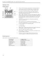
Display interface
1
On Line
—
The UPS is supplying utility power to connected equipment
2
Power-Saving
—
Master and controlled outlets are enabled, saving
power when the master device goes into sleep or standby mode
3
Load Capacity
—
The load is indicated by the number of sections
illuminated, one to five. If the load exceeds the rated capacity, the
Overload symbol will flash off and on.
4
Battery Charge
—
The battery charge level is indicated by the number of
sections illuminated. When all five blocks are illuminated, the Back-UPS
is at full charge. When one block is filled, the Back-UPS is near the end
of its battery capacity, the indicator will flash and the unit will beep
continuously.
5
Overload
—
The power demand from the load has exceeded the
capacity of the Back-UPS.
6
Event
—
An event has occurred and the unit needs attention.
7
Automatic Voltage Regulation
—
The unit is compensating for extremely
low input voltage, but is not using battery power.
8
In
—
Input voltage.
Out
—
Output voltage.
9
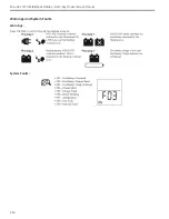
System Faults
—
The system has a fault. The fault number will illuminate
on the display interface. See “System Faults” on page 4.
10
Mute
—
The audible alarm has been turned off.
11
Replace Battery
—
The battery is not connected or is nearing the end of
its useful life. Replace the battery.
12
On Battery
—
The unit is supplying battery backup power to the
connected equipment, it will beep four times every 30 seconds.
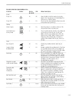
Modes of operation
Press DISPLAY to scroll through the display screens.
On Line Mode
On Battery Mode
Input Voltage
Estimated runtime in minutes
Counter Power
Event Counter
Estimated run time
Output Voltage
Load in Watts
Input Voltage
Load in %
Load in Watts
Output
Voltage Load in %
Output Frequency
Output Frequency
Содержание Brivo OEC 715
Страница 2: ......
Страница 19: ...Chapter1 Introduction and Safety...
Страница 41: ...Introduction and Safety 23 46 54 20 18 26...
Страница 55: ...Chapter2 System Overview...
Страница 137: ...Chapter3 Installation...
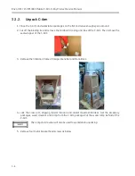
Страница 147: ...Installation 3 11 7 Put the ramp in position Release all bracket and move the workstation along the ramp off the pallet...
Страница 211: ...Installation 3 75 3 9 Reporting For U S Systems Complete and submit Form 2579 within 15 days of installation...
Страница 212: ...Chapter4 Calibration...
Страница 223: ...Brivo OEC 715 785 865 Mobile C Arm X Ray Product Service Manual 4 12 Mainframe Control Board TP7...
Страница 231: ...Brivo OEC 715 785 865 Mobile C Arm X Ray Product Service Manual 4 20 Mainframe Control Board TP17 POT4 J5 TP7 POT7 POT5...
Страница 275: ...Brivo OEC 715 785 865 Mobile C Arm X Ray Product Service Manual 4 64...
Страница 284: ...Chapter5 Software...
Страница 312: ...Software 5 29 4 Click Next 5 Click Install 6 Click Finish button to complete installation procedure...
Страница 326: ...Software 5 43 2 Click on install to continue 3 Click Next to continue...
Страница 335: ...Chapter6 Troubleshooting...
Страница 408: ...Chapter7 Replacement...
Страница 418: ...Replacement 7 11 166...
Страница 488: ...Chapter8 Periodic Maintenance...
Страница 502: ...Periodic Maintenance 8 15...
Страница 505: ...Chapter9 Technical Reference...
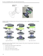
Страница 520: ...Brivo OEC 715 785 865 Mobile C Arm X Ray Product Service Manual 9 16 Lateral configuration 1 5m Lateral configuration 1m...
Страница 521: ...Technical Reference 9 17 Vertical configuration 1 5m Vertical configuration 1m...
Страница 526: ...11 Appendix System Schematics...

