Installation
3-47
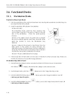
Low dose Fluoro Dose rate check:
1.
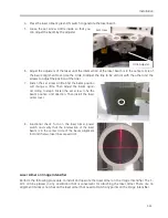
Position the detector of dosimeter at the center of the X-ray beam 30cm above the grid of image
intensifier. Cover the image intensifier with lead plate thicker than 3mm.
2.
Set kVp as 110kVp, increase mA to maximum in manual mode. Measure the dose rate while
making exposure. Limits vary by the dose group, which was selected in software configuration
section by country.
3.
Refer to below table verify the corresponding Dose group according to country’s Dose group
requirement (refer to 5.2.4).
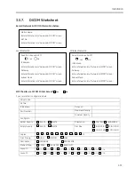
Continuous Fluoro
≤
47.5 mGy/min (Dose group: Normal 50 and HLF 50)
≤
47.5 mGy/min (Dose group: Normal 50 and HLF 100)
≤
83.6 mGy/min (Dose group: Normal 88 and HLF 100)
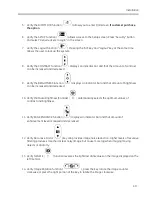
Low dose HLF Dose rate check:
1.
Position the dosimeter in the center of the X-ray beam 30cm above the grid. Cover the image
intensifier with lead thicker than 3mm for protection of the image intensifier.
2.
Set kVp as 110kVp, increase mA to maximum in manual mode. Measure the dose rate while
making exposure. Limits vary by the dose group, which was selected in software configuration
section by country.
3.
Refer to below table verify the corresponding Dose group according to country’s Dose group
requirement (refer to 5.2.4).
Continuous Fluoro
≤
47.5 mGy/min (Dose group: Normal 50 and HLF 50)
≤
95 mGy/min (Dose group: Normal 50 and HLF 100)
≤
95 mGy/min (Dose group: Normal 88 and HLF 100)
3.6.6.
Beam Alignment Check
Refer to chapter 4.6 performance Beam Alignment Check.
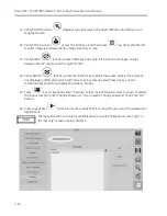
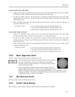
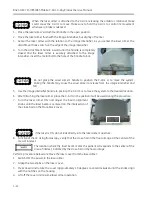
German regulatory required that the collimator has to be visible on
two sides of the image, which are not opposite. For the system
installed in German, adjust collimator iris until the collimator meet
the requirement as below.
Australia regulatory required that the beam limiting device must
automatically limit the primary beam to X-ray image receptor area
(within 1% SID), which it must set to the selected field of the I.I. or image receptor in the
fluoroscopic mode. For the system installed in Australia, adjust collimator iris until the
collimator 8 leaves can be seen in the image.
3.6.7.
DAP Accuracy Check
Refer to chapter 4.7 to do DAP accuracy check.
3.6.8.
System Status Backup
Refer chapter 5, export system setup and administration configuration, if needed.
Содержание Brivo OEC 715
Страница 2: ......
Страница 19: ...Chapter1 Introduction and Safety...
Страница 41: ...Introduction and Safety 23 46 54 20 18 26...
Страница 55: ...Chapter2 System Overview...
Страница 137: ...Chapter3 Installation...
Страница 147: ...Installation 3 11 7 Put the ramp in position Release all bracket and move the workstation along the ramp off the pallet...
Страница 211: ...Installation 3 75 3 9 Reporting For U S Systems Complete and submit Form 2579 within 15 days of installation...
Страница 212: ...Chapter4 Calibration...
Страница 223: ...Brivo OEC 715 785 865 Mobile C Arm X Ray Product Service Manual 4 12 Mainframe Control Board TP7...
Страница 231: ...Brivo OEC 715 785 865 Mobile C Arm X Ray Product Service Manual 4 20 Mainframe Control Board TP17 POT4 J5 TP7 POT7 POT5...
Страница 275: ...Brivo OEC 715 785 865 Mobile C Arm X Ray Product Service Manual 4 64...
Страница 284: ...Chapter5 Software...
Страница 312: ...Software 5 29 4 Click Next 5 Click Install 6 Click Finish button to complete installation procedure...
Страница 326: ...Software 5 43 2 Click on install to continue 3 Click Next to continue...
Страница 335: ...Chapter6 Troubleshooting...
Страница 408: ...Chapter7 Replacement...
Страница 418: ...Replacement 7 11 166...
Страница 488: ...Chapter8 Periodic Maintenance...
Страница 502: ...Periodic Maintenance 8 15...
Страница 505: ...Chapter9 Technical Reference...
Страница 520: ...Brivo OEC 715 785 865 Mobile C Arm X Ray Product Service Manual 9 16 Lateral configuration 1 5m Lateral configuration 1m...
Страница 521: ...Technical Reference 9 17 Vertical configuration 1 5m Vertical configuration 1m...
Страница 526: ...11 Appendix System Schematics...

