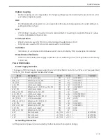
System Overview
2-21
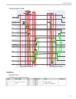
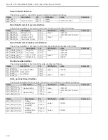
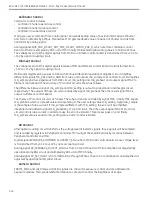
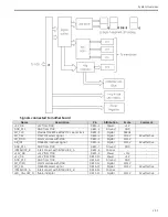
Digital signals LIH is through optical coupling circuit from Peripheral controller of MCB to Camera. Digital
signal FRAME_SYNC is from Camera to MCB. It is the global synchronization signal of X-Ray control function,
so it acts as clock and interrupt signal to peripheral controller and MCU, respectively.
GAIN signal from MCB to camera is through RS485 bus.
Image Intensifier Control
II control here means II field switch only. F1/F2 signals are controlled by MCU directly.
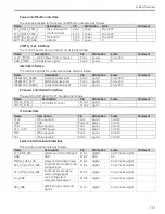
Digital signals (F1/F2) are from MCB to II. The voltage level of those signals is transformed from +3.3V to +24V
by optical coupling circuit.
MCB outputs IDRG_HC signal to control the relay. When the relay is close, II_PWR is connected with +24V
and II_GND is connected with GND_+24V. Therefore, II is power-on. When the relay is open, II_PWR and
II_GND are both connected to GND_+24V, and then II is power-off.
Sealing Board
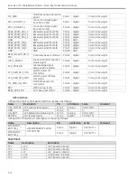
Analog signals KV_GND and MA_CAT are the anode and cathode of mA current signal, respectively. The
current transforms to voltage signal by flowing through a resistor. ADC unit of MCU in MCB samples this
signal after its scale is transformed to 0-2.5V by operational amplifier circuit.
There are two temperature measurement circuits in sealing board. One’s output is analog signal OIL_TEMP,
whose scale is 0-2V. ADC unit of MCU in MCB samples this signal after its scale is transformed to 0-2.5V by
operational amplifier circuit. MCU will compare this value with preset threshold to generate oil tank warm
warning and hot alarm.
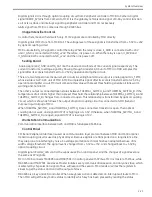
The other’s output is connected/open status between THERMAL_SWITCH_A and THERMAL_SWITCH_B. If the
temperature of oil tank is higher than a preset threshold, the relationship between THERMAL_SWITCH_A and
THERMAL_SWITCH_B changes from connected to open. This relationship is transformed by optical coupling
circuit, which is shown as follows. The output of optical coupling circuit is connected to GPIO (General
Purpose Input Output) of MCU.
When THERMAL_SWITCH_A and THERMAL_SWITCH_B are connected, transistor is open. Then optical
coupling do not work, and signal OUTPUT is high logic at +3.3V. Otherwise, when THERMAL_SWITCH_A and
THERMAL_SWITCH_B are open, signal OUTPUT is low logic at 0V.
Workstation Communication
Communication interface between WK and MCB is full duplex RS485 bus.
Control Panel
SPI (Serial Peripheral Interface) is used as communication layer protocol between MCB and Control panel.
Optical coupling circuit is used as physical layer. Because signals are transported on a long distance line,
they are prone to interfering by noise. So voltage promotion technical has been adopted because of its
width voltage threshold. The signal level is changed from +3.3V to +15V, and changed back to +3.3V by
optical coupling circuit.
Digital signal YELLOW_LED control the exposure LED on control panel, and the changes of signal level are
the same as SPI signals.
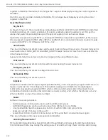
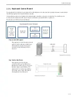
MCU in MCB connects MAX6954 and MAX7301 in Control panel with SPI bus. MCU is master of SPI bus, while
MAX6954 and MAX7301 are slaves. Master initiates every communication session, and only one slave, which
is selected by chip selection signal of bus, will respond the session. MCU reads or writes the registers in
slaves to get the status and control the output of slave.
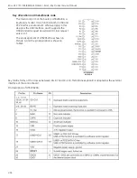
MAX6954 is a key and LED controller. When a key press action is detected, an interrupt will route to MCU.
Then MCU will get the key matrix status to identify which key has been pressed by reading the status
Содержание Brivo OEC 715
Страница 2: ......
Страница 19: ...Chapter1 Introduction and Safety...
Страница 41: ...Introduction and Safety 23 46 54 20 18 26...
Страница 55: ...Chapter2 System Overview...
Страница 137: ...Chapter3 Installation...
Страница 147: ...Installation 3 11 7 Put the ramp in position Release all bracket and move the workstation along the ramp off the pallet...
Страница 211: ...Installation 3 75 3 9 Reporting For U S Systems Complete and submit Form 2579 within 15 days of installation...
Страница 212: ...Chapter4 Calibration...
Страница 223: ...Brivo OEC 715 785 865 Mobile C Arm X Ray Product Service Manual 4 12 Mainframe Control Board TP7...
Страница 231: ...Brivo OEC 715 785 865 Mobile C Arm X Ray Product Service Manual 4 20 Mainframe Control Board TP17 POT4 J5 TP7 POT7 POT5...
Страница 275: ...Brivo OEC 715 785 865 Mobile C Arm X Ray Product Service Manual 4 64...
Страница 284: ...Chapter5 Software...
Страница 312: ...Software 5 29 4 Click Next 5 Click Install 6 Click Finish button to complete installation procedure...
Страница 326: ...Software 5 43 2 Click on install to continue 3 Click Next to continue...
Страница 335: ...Chapter6 Troubleshooting...
Страница 408: ...Chapter7 Replacement...
Страница 418: ...Replacement 7 11 166...
Страница 488: ...Chapter8 Periodic Maintenance...
Страница 502: ...Periodic Maintenance 8 15...
Страница 505: ...Chapter9 Technical Reference...
Страница 520: ...Brivo OEC 715 785 865 Mobile C Arm X Ray Product Service Manual 9 16 Lateral configuration 1 5m Lateral configuration 1m...
Страница 521: ...Technical Reference 9 17 Vertical configuration 1 5m Vertical configuration 1m...
Страница 526: ...11 Appendix System Schematics...

