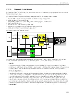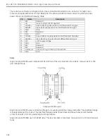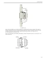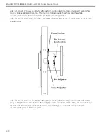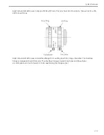
System Overview
2-57
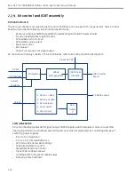
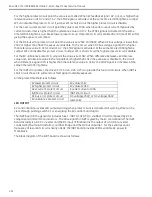
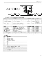
When filament focus switches, PWM pulses will shut down for a while delay of 56mS, because operate time
of relay is about 7mS and RC circuit of coil of relay costs about 6mS. The delay time should be more than
13mS. The delay signal is produced by CD4538 and logic gates. The delay time is determined by R42, C29
and R41, C28.
10V reference
The U7 REF102 chip provides st10V for regulating circuit.
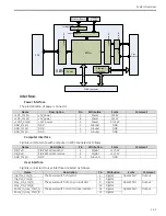
Interlock
The J1A-13 and J1C-13 pin of connector are connected as interlock. The interlock goes through the FDB to
verify that the FDB is in place.
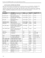
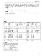
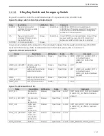
Interface
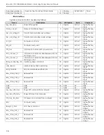
Name
Description
Pin
Attribution
Scale
Comment
GND
GND
J1A-12, J1A-32, J1B-12, J1C-12,
Ground
GND
GND
15V
+15V
J1A-29, J1B-29, J1C-29
Power
15V
15V
15NV
-15V
J1C-32
Power
-15V
-15V
24V
+24V
J1A-1, J1B-1, J1C-1
Power
+24V
+24V
24V_GND
GND of 24V
J1A-6, J1B-6, J1C-6
Ground
GND
GND of 24V
MAC_FDB
Set current value
J1B-9
Analog
0V~15V
PWMC_FDB
Control voltage
output
J1B-13
Analog
-15V~15V
FILDIS_FDB
Filament disable
J1C-10
Digital
0V/15V
15V=effective
FCSSW_FDB
Large or small
filament switch
J1A-10
Digital
0V/15V
0V= small
15V=large
OCALM_FDB
Over current alarm
signal output
J1B-10
Digital
0V/15V
15V=effective
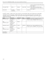
FILLA2
Large filament
J1A-18, J1B-18, J1C-18
Analog
0V~24V
FILLA1
Large filament
J1A-20, J1B-20, J1C-20
Analog
0V~24V
FILSM1
Small filament
J1A-22, J1B-22, J1C-22
Analog
0V~24V
FILSM2
Small filament
J1A-24, J1B-24, J1C-24
Analog
0V~24V
FILCOM
Filament common
port
J1A-26, J1B-26, J1C-26
Analog
0V~24V
Interlock_B
Interlock_B
J1A-13
Digital
0V/24V
Interlock_C
Interlock_C
J1C-13
Digital
0V/24V
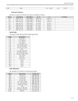
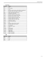
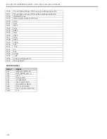
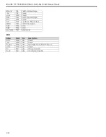
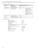
Test point
Name
Pin
Description
FC
TP1
Return current
PWMB
TP2
PWM drive signal
OC
TP3
Overcurrent
FC_RC
TP4
Filtered return current
+15V
TP5
Power
GND
TP6
GND
SMAC
TP7
PWM control voltage
Содержание Brivo OEC 715
Страница 2: ......
Страница 19: ...Chapter1 Introduction and Safety...
Страница 41: ...Introduction and Safety 23 46 54 20 18 26...
Страница 55: ...Chapter2 System Overview...
Страница 137: ...Chapter3 Installation...
Страница 147: ...Installation 3 11 7 Put the ramp in position Release all bracket and move the workstation along the ramp off the pallet...
Страница 211: ...Installation 3 75 3 9 Reporting For U S Systems Complete and submit Form 2579 within 15 days of installation...
Страница 212: ...Chapter4 Calibration...
Страница 223: ...Brivo OEC 715 785 865 Mobile C Arm X Ray Product Service Manual 4 12 Mainframe Control Board TP7...
Страница 231: ...Brivo OEC 715 785 865 Mobile C Arm X Ray Product Service Manual 4 20 Mainframe Control Board TP17 POT4 J5 TP7 POT7 POT5...
Страница 275: ...Brivo OEC 715 785 865 Mobile C Arm X Ray Product Service Manual 4 64...
Страница 284: ...Chapter5 Software...
Страница 312: ...Software 5 29 4 Click Next 5 Click Install 6 Click Finish button to complete installation procedure...
Страница 326: ...Software 5 43 2 Click on install to continue 3 Click Next to continue...
Страница 335: ...Chapter6 Troubleshooting...
Страница 408: ...Chapter7 Replacement...
Страница 418: ...Replacement 7 11 166...
Страница 488: ...Chapter8 Periodic Maintenance...
Страница 502: ...Periodic Maintenance 8 15...
Страница 505: ...Chapter9 Technical Reference...
Страница 520: ...Brivo OEC 715 785 865 Mobile C Arm X Ray Product Service Manual 9 16 Lateral configuration 1 5m Lateral configuration 1m...
Страница 521: ...Technical Reference 9 17 Vertical configuration 1 5m Vertical configuration 1m...
Страница 526: ...11 Appendix System Schematics...

