Brivo OEC 715/785/865/865 Mobile C-Arm X-Ray Product Service Manual
2-24
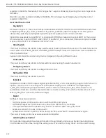
Interface
Overview
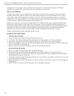
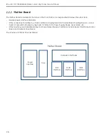
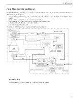
MCB is plugged in Mother Board, and is connected with other sub-systems through Mother Board. The
electrical interface of Mother Board, please refer to Motherboard section.
The external physical interfaces of MCB are defined in the table below:
Connector
Name
Type
Gender
Description
J1
MCB digital
signal
connector
DN41612 C
Type Male
Pin
All digital signals from/to other sub-system, such as
collimator board, filament board, sealing board, camera,
KV control board etc.
J2
MCB analog
signal
connector
DN41612 Half
C Type Male
Pin
All analog signals from/to other sub-system, such as
collimator board, filament board, sealing board, camera,
KV control board etc.
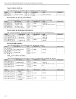
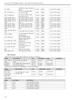
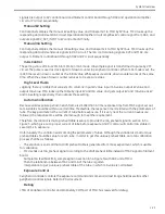
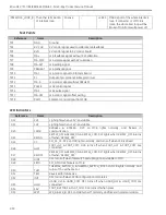
Collimator Control
Signals from MCB to collimator control board are listed as follows.
Name
Description
Attribution
Scale
Pin
Comment
SPI_SCLK_CCB
SPI clock signal
Digital
0V/+15V
J1-B22
-
SPI_DIN_CCB
SPI data from MCB to CCB
Digital
0V/+15V
J1-C19
-
SPI_SYNC_CCB
SPI chip select signal
Digital
0V/+15V
J1-A21
+15V=effective
RSV_CCB
Reversed for future
Digital
0V/+15V
J1-B15
-
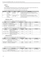
Signals from collimator control board to MCB are listed as follows.
Name
Description
Attribution
Scale
Pin
Comment
IRIS_POS_F
Feedback voltage from Iris
position rheostat
Analog
0-5V
J2-C12
-
SHUT_ROT_POS_F
Feedback voltage from shutter
rotation position rheostat
Analog
0-5V
J2-A12
-
SHUT_WIDTH_POS_F Feedback voltage from shutter
width position rheostat
Analog
0-5V
J2-B12
-
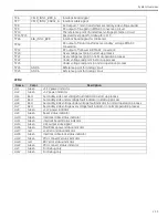
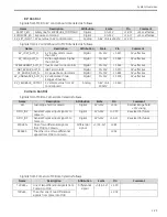
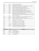
Filament Control
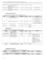
Signals from MCB to filament control board are listed as follows.
Name
Description
Attribution
Scale
Pin
Comment
FILDIS_FDB
System general alarm to disable
filament current, Trigger by anyone of
several alarms
Digital
0/+15V
J1-B14
+15V= effective
FCSSW_FDB Large focus function selected
Digital
0/+15V
J1-A15
+15V= effective
MAC_FDB
Fluoro mA control signal
Analog
3.0-5.0V
J2-C11
-
Signals from filament control board to MCB are listed as follows.
Name
Description
Attribution
Scale
Pin
Comment
OCALM_FDB Overcurrent alarm of +24V power
supply in filament board
Digital
0/+15V
J1-C16
+15V= effective
PWMC_FDB
PWM control signal of filament current
Analog
0/+15V
J2-B11
-
Содержание Brivo OEC 715
Страница 2: ......
Страница 19: ...Chapter1 Introduction and Safety...
Страница 41: ...Introduction and Safety 23 46 54 20 18 26...
Страница 55: ...Chapter2 System Overview...
Страница 137: ...Chapter3 Installation...
Страница 147: ...Installation 3 11 7 Put the ramp in position Release all bracket and move the workstation along the ramp off the pallet...
Страница 211: ...Installation 3 75 3 9 Reporting For U S Systems Complete and submit Form 2579 within 15 days of installation...
Страница 212: ...Chapter4 Calibration...
Страница 223: ...Brivo OEC 715 785 865 Mobile C Arm X Ray Product Service Manual 4 12 Mainframe Control Board TP7...
Страница 231: ...Brivo OEC 715 785 865 Mobile C Arm X Ray Product Service Manual 4 20 Mainframe Control Board TP17 POT4 J5 TP7 POT7 POT5...
Страница 275: ...Brivo OEC 715 785 865 Mobile C Arm X Ray Product Service Manual 4 64...
Страница 284: ...Chapter5 Software...
Страница 312: ...Software 5 29 4 Click Next 5 Click Install 6 Click Finish button to complete installation procedure...
Страница 326: ...Software 5 43 2 Click on install to continue 3 Click Next to continue...
Страница 335: ...Chapter6 Troubleshooting...
Страница 408: ...Chapter7 Replacement...
Страница 418: ...Replacement 7 11 166...
Страница 488: ...Chapter8 Periodic Maintenance...
Страница 502: ...Periodic Maintenance 8 15...
Страница 505: ...Chapter9 Technical Reference...
Страница 520: ...Brivo OEC 715 785 865 Mobile C Arm X Ray Product Service Manual 9 16 Lateral configuration 1 5m Lateral configuration 1m...
Страница 521: ...Technical Reference 9 17 Vertical configuration 1 5m Vertical configuration 1m...
Страница 526: ...11 Appendix System Schematics...

