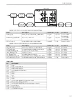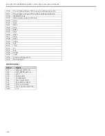
System Overview
2-39
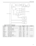
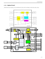
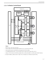
PMOSFET Driver
This circuit is to control the PMOSFET so that the DC voltage would not higher than 37V+/-5%. When the DC
voltage is higher than 37V+/-5% the PMOSFET would turn off. When the DC voltage is lower than 29V+/-5%
the PMOSFET would turn on.
Motor Current Detector
This circuit is to detect the motor current. There are two current limit values. One is for the up motion. The
other is for the down motion. When the motor current is larger than the limit value, the overcurrent signal
would send out to stop the motion.
Key Switch Sensor
This circuit is to detect the key switch signal to control the motor motion. When the key switch is at the OFF
state the output of this circuit would be high level and the motor motion would be disabled.
Motion DIS/ENA
This circuit is to detect the UDB_ENABLE signal from MCB to control the motor motion. When the
UDB_ENABLE signal is low level the output of this circuit would be high level and the motor motion would be
disabled.
Proximity Switch Protector
This circuit is to detect the state of the proximity switch to control the motor motion. When the motor is
down to the proximity protect position the output of this circuit would be high level and the motor would be
stopped.
Interlock Protector
There are many factures to affect the motor motion including up key, down key, down_security key, motor
current, key switch, proximity switch and motion DIS/ENA. This circuit is to combine these features to control
Relay K9 and then to realize the control of the motor.
-
When any signal from motor current, key switch, proximity switch and motion DIS/ENA is to disable the
motor motion, relay K9 would turn on and HL5 would be bright. The DC voltage of the motor would down
to zero. And then the motor stops.
-
The interlock function of motor current and keys are realized in this circuit. When the motor current is
overloaded the motor would be disabled to motion and HL4 and HL5 would be bright. Only when all the
keys are released the HL4 and HL5 can be dark. And then the motor motion is enabled.
-
The interlock function of keys and proximity switch are realized in this circuit. When the motor down to
the proximity protect position HL5 shall be bright and the motor shall stop. Only when all the keys are
released the HL5 can be dark. And then press both the down key and the down_security key at the same
time. The motor begins down motion.
Содержание Brivo OEC 715
Страница 2: ......
Страница 19: ...Chapter1 Introduction and Safety...
Страница 41: ...Introduction and Safety 23 46 54 20 18 26...
Страница 55: ...Chapter2 System Overview...
Страница 137: ...Chapter3 Installation...
Страница 147: ...Installation 3 11 7 Put the ramp in position Release all bracket and move the workstation along the ramp off the pallet...
Страница 211: ...Installation 3 75 3 9 Reporting For U S Systems Complete and submit Form 2579 within 15 days of installation...
Страница 212: ...Chapter4 Calibration...
Страница 223: ...Brivo OEC 715 785 865 Mobile C Arm X Ray Product Service Manual 4 12 Mainframe Control Board TP7...
Страница 231: ...Brivo OEC 715 785 865 Mobile C Arm X Ray Product Service Manual 4 20 Mainframe Control Board TP17 POT4 J5 TP7 POT7 POT5...
Страница 275: ...Brivo OEC 715 785 865 Mobile C Arm X Ray Product Service Manual 4 64...
Страница 284: ...Chapter5 Software...
Страница 312: ...Software 5 29 4 Click Next 5 Click Install 6 Click Finish button to complete installation procedure...
Страница 326: ...Software 5 43 2 Click on install to continue 3 Click Next to continue...
Страница 335: ...Chapter6 Troubleshooting...
Страница 408: ...Chapter7 Replacement...
Страница 418: ...Replacement 7 11 166...
Страница 488: ...Chapter8 Periodic Maintenance...
Страница 502: ...Periodic Maintenance 8 15...
Страница 505: ...Chapter9 Technical Reference...
Страница 520: ...Brivo OEC 715 785 865 Mobile C Arm X Ray Product Service Manual 9 16 Lateral configuration 1 5m Lateral configuration 1m...
Страница 521: ...Technical Reference 9 17 Vertical configuration 1 5m Vertical configuration 1m...
Страница 526: ...11 Appendix System Schematics...

