Brivo OEC 715/785/865/865 Mobile C-Arm X-Ray Product Service Manual
2-20
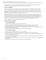
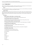
Collimator Control
Collimator control includes
- Collimator Shutter open/close control
- Collimator Shutter rotation control
- Collimator Iris open/close control
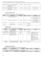
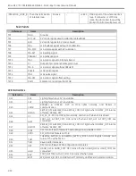
MCU gets user’s command from Control panel, and sends setting value of position information of Shutter
and Iris to Collimator by SPI bus. Meanwhile, MCU gets feedback value of position of Shutter and Iris from
Collimator by analog signal.
Analog signals (IRIS_POS_F/SHUT_ROT_POS_F/SHUT_WIDTH_POS_F), which are from collimator control
board to MCB, are sampled by ADC unit of MCU finally. MCB sends digital setting values to CCB via SPI bus.
The voltage level of all the digital signals from MCB to collimator control board is transformed from +3.3V to
+15V by optical coupling circuit.
Filament Control
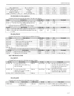
The voltage level of all the digital signals between MCB and filament control board are transformed from
+3.3V to +15V by optical coupling circuit.
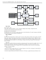
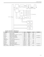
MCB sends digital setting values to DAC with SPI bus. Differential operational amplifier circuit amplifies
differential signals MA_CAT and KV_GND from tube, and outputs mA_sample to PI control circuit. PI amplifies
mA_sample and two signals out from DAC circuit, mA_setting and mA_preheat, and outputs signal MAC to
filament control board. The structure of PI control circuit is shown as follows.
The difference between signal mA_sample and mA_setting is output to proportional and integral circuit,
respectively. The outputs of those circuits are added by signal mA_preheat, then the result signal MAC is
output to filament control board.
The theory of PI control circuit is as follows. The tube current is controlled by signal MAC. Initially MAC equals
mA_preheat, which is a preset value corresponding to the user setting value mA_setting. Signal mA_sample
is the sample of tube current. If mA_sample is different with mA_setting, the error will be amplified,
integrated and added to signal mA_preheat by PI control circuit. Then the output signal MAC of PI control
circuit controls tube current in order to make the error be smaller. This process goes on, and finally
mA_sample value is equal to mA_setting value, and PI control is stable.
KV Control
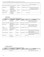
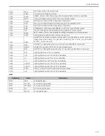
After optical coupling circuit transforms the voltage level of 6 alarm signals, those signals will be sampled
and recorded by registers in Peripheral Controller. MCU will get these alarm status by local bus between
Peripheral Controller and MCU.
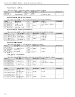
Digital signal EXPOSURE_COMMAND and SAFETY_EN are from MCB to KV control board, whose voltage level
is transformed from +3.3V to +15V by optical coupling circuit.
Analog signal KV_FEEDBACK_OUTPUT, which is from KV control board to MCB, is amplified (or adjusted) by
operational amplifier circuit and sampled by ADC unit of MCU finally.
Analog signal KV_SET_INPUT is from MCB to DAC through SPI bus, then to KV control board, and amplified (or
adjusted) by operational amplifier circuit.
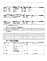
Camera Control
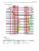
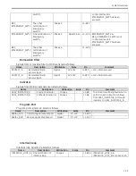
FRAME_SYNC and Last Image Hold (LIH) signals are critical for exposure control and are addressed in
exposure module. MCU sends GAIN information to camera to control the brightness of image.
Содержание Brivo OEC 715
Страница 2: ......
Страница 19: ...Chapter1 Introduction and Safety...
Страница 41: ...Introduction and Safety 23 46 54 20 18 26...
Страница 55: ...Chapter2 System Overview...
Страница 137: ...Chapter3 Installation...
Страница 147: ...Installation 3 11 7 Put the ramp in position Release all bracket and move the workstation along the ramp off the pallet...
Страница 211: ...Installation 3 75 3 9 Reporting For U S Systems Complete and submit Form 2579 within 15 days of installation...
Страница 212: ...Chapter4 Calibration...
Страница 223: ...Brivo OEC 715 785 865 Mobile C Arm X Ray Product Service Manual 4 12 Mainframe Control Board TP7...
Страница 231: ...Brivo OEC 715 785 865 Mobile C Arm X Ray Product Service Manual 4 20 Mainframe Control Board TP17 POT4 J5 TP7 POT7 POT5...
Страница 275: ...Brivo OEC 715 785 865 Mobile C Arm X Ray Product Service Manual 4 64...
Страница 284: ...Chapter5 Software...
Страница 312: ...Software 5 29 4 Click Next 5 Click Install 6 Click Finish button to complete installation procedure...
Страница 326: ...Software 5 43 2 Click on install to continue 3 Click Next to continue...
Страница 335: ...Chapter6 Troubleshooting...
Страница 408: ...Chapter7 Replacement...
Страница 418: ...Replacement 7 11 166...
Страница 488: ...Chapter8 Periodic Maintenance...
Страница 502: ...Periodic Maintenance 8 15...
Страница 505: ...Chapter9 Technical Reference...
Страница 520: ...Brivo OEC 715 785 865 Mobile C Arm X Ray Product Service Manual 9 16 Lateral configuration 1 5m Lateral configuration 1m...
Страница 521: ...Technical Reference 9 17 Vertical configuration 1 5m Vertical configuration 1m...
Страница 526: ...11 Appendix System Schematics...

