Brivo OEC 715/785/865/865 Mobile C-Arm X-Ray Product Service Manual
2-10
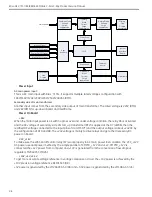
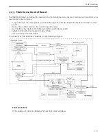
An Altera CPLD U1 is used as main controller on the board; it controls most of the relays on the board,
generates the signal by the user interface and communicates with SIB board
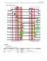
Power on scheduling
To achieve the inrush current suppression for the primary side of the main transformer, power resistors R
(15Ohm, 50W) shall be used in system configuration. Approximately 2 seconds after power with no gross
over/under voltage fault is applied by the relay K1, relay K2 closes, bypassing the resistors R, reducing IR
voltage drop, and allowing them to cool. To avoid the risk that the resistor R will be heated and burned when
the K2 is in failure, relay K1 shall be energized for only about 1s.
Similarly, to achieve the inrush current suppression for the mainframe side, power resistors R(15Ohm,50W)
shall be also used in the secondary side of main transformer. The 220V voltage winding is applied to the
mainframe by the K3 and K4. When the secondary voltage of main transformer with no load is OK, K3 will be
energized first, then the K4 closes to shorten the R to reduce the power loss, the K3 will be energized for
about 1s to avoid the risk that the resistor R will be heated and burned when the K4 is in failure.
The 28V voltage winding is directly applied by the relay K5.
UPS status for Power On/Off
Normal Power off system
1.
Power on system and inspect UPS button led and LCD status.
2.
Front three LEDs and LCD backlight are lighted up, then a beep happen, LCD shows UPS status.
3.
At that time, system will boot up successfully, then power off system. And inspect UPS status.
4.
After system software exits successfully, a beep happen again, LCD shows nothing, but front three LEDs
and LCD backlight are still lighted up.
5.
After 1 minute to 5 minutes, front three LEDs and LCD backlight extinguish.
Abnormal Power off system
1.
Power on system and inspect UPS button led and LCD status.
2.
Front three LEDs and LCD backlight are lighted up, then a beep happen, LCD shows UPS status.
3.
At that time, system will boot up successfully, then unplug system AC power (please make sure battery is
fully charged) and inspect UPS status.
4.
UPS works on battery mode and gives four beeps every 30 seconds, and system software find AC lost and
power off system automatically.
5.
After system software exits successfully, LCD shows nothing, but front three LEDs and LCD backlight are
still lighted up.
6.
After 1 minute to 5 minutes, front three LEDs and LCD backlight extinguish.
Содержание Brivo OEC 715
Страница 2: ......
Страница 19: ...Chapter1 Introduction and Safety...
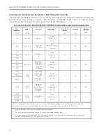
Страница 41: ...Introduction and Safety 23 46 54 20 18 26...
Страница 55: ...Chapter2 System Overview...
Страница 137: ...Chapter3 Installation...
Страница 147: ...Installation 3 11 7 Put the ramp in position Release all bracket and move the workstation along the ramp off the pallet...
Страница 211: ...Installation 3 75 3 9 Reporting For U S Systems Complete and submit Form 2579 within 15 days of installation...
Страница 212: ...Chapter4 Calibration...
Страница 223: ...Brivo OEC 715 785 865 Mobile C Arm X Ray Product Service Manual 4 12 Mainframe Control Board TP7...
Страница 231: ...Brivo OEC 715 785 865 Mobile C Arm X Ray Product Service Manual 4 20 Mainframe Control Board TP17 POT4 J5 TP7 POT7 POT5...
Страница 275: ...Brivo OEC 715 785 865 Mobile C Arm X Ray Product Service Manual 4 64...
Страница 284: ...Chapter5 Software...
Страница 312: ...Software 5 29 4 Click Next 5 Click Install 6 Click Finish button to complete installation procedure...
Страница 326: ...Software 5 43 2 Click on install to continue 3 Click Next to continue...
Страница 335: ...Chapter6 Troubleshooting...
Страница 408: ...Chapter7 Replacement...
Страница 418: ...Replacement 7 11 166...
Страница 488: ...Chapter8 Periodic Maintenance...
Страница 502: ...Periodic Maintenance 8 15...
Страница 505: ...Chapter9 Technical Reference...
Страница 520: ...Brivo OEC 715 785 865 Mobile C Arm X Ray Product Service Manual 9 16 Lateral configuration 1 5m Lateral configuration 1m...
Страница 521: ...Technical Reference 9 17 Vertical configuration 1 5m Vertical configuration 1m...
Страница 526: ...11 Appendix System Schematics...

