Brivo OEC 715/785/865/865 Mobile C-Arm X-Ray Product Service Manual
2-38
THEORY OF OPERATION
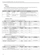
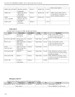
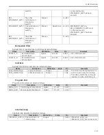
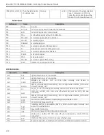
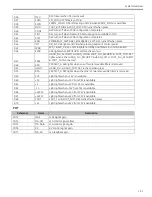
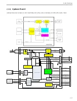
Power Regulator
This circuit is to translate the DC24V input to the DC+15V and DC+2.5V which would be used in the updown
board. Devices 7815 and LM431 are used to realize this function.
AC-DC
Translate the AC28V input to the DC output.
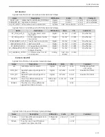
Up/down relays
This function is to realize the up and down motion. Different polar voltage would be added to the lift column
motor by these relays.
Relay K9 is closed-normal. When the motor is forbidden motioning, K9 shall turn on and this closed-normal
contact shall open.
When the up motion is enabled, relays K1-K4 shall turn on and relays K5-K8 shall turn off. And the positive
DC voltage shall apply to the lift column motor. The voltage of the signal MOTO1 shall higher than MOTO2
and the motor begins up motion.
When the down motion is enabled, relays K5-K8 shall turn on and relays K1-K4 shall turn off. And the
negative DC voltage shall apply to the lift column motor. The voltage of the signal MOTO2 shall higher than
MOTO1 and the motor begins down motion.
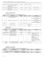
Up/down control relays
This circuit is to control the relays in Up/down relays circuit according to the commands from Up/down Key
Control & Delay circuit.
Up/down Key Control & Delay
This circuit is to translate the up, down, down_security signals to the UP_COMMAND and DOWN_COMMAND
signals to control the relays and the motor motion. It includes two basic functions: delay control function and
motion control function.
-
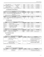
Motion control function
When only the up key is pressed the UP_COMMAND signal shall be high level.
When the motor is not at the proximity protect position and only the down key is pressed, the DOWN_COMMAND
signal shall be high level.
When the motor is at the proximity protect position and both the down key and down_security key are pressed,
the DOWN_COMMAND signal shall be high level.
When both of the up key and the down key are pressed the motor shall stop. The signal UP_COMMAND and the
signal DOWN_COMMAND shall be low level.
-
delay control function
The Updown board shall receive the lift column up or down command and then drive the motor motion with
a few milliseconds delay. The RC delay circuit is used to realize this function.
Voltage Detector
This function is to detect the DC voltage through the resistor divider. The output of this circuit is the input of
the PMOSFET Driver circuit.
Содержание Brivo OEC 715
Страница 2: ......
Страница 19: ...Chapter1 Introduction and Safety...
Страница 41: ...Introduction and Safety 23 46 54 20 18 26...
Страница 55: ...Chapter2 System Overview...
Страница 137: ...Chapter3 Installation...
Страница 147: ...Installation 3 11 7 Put the ramp in position Release all bracket and move the workstation along the ramp off the pallet...
Страница 211: ...Installation 3 75 3 9 Reporting For U S Systems Complete and submit Form 2579 within 15 days of installation...
Страница 212: ...Chapter4 Calibration...
Страница 223: ...Brivo OEC 715 785 865 Mobile C Arm X Ray Product Service Manual 4 12 Mainframe Control Board TP7...
Страница 231: ...Brivo OEC 715 785 865 Mobile C Arm X Ray Product Service Manual 4 20 Mainframe Control Board TP17 POT4 J5 TP7 POT7 POT5...
Страница 275: ...Brivo OEC 715 785 865 Mobile C Arm X Ray Product Service Manual 4 64...
Страница 284: ...Chapter5 Software...
Страница 312: ...Software 5 29 4 Click Next 5 Click Install 6 Click Finish button to complete installation procedure...
Страница 326: ...Software 5 43 2 Click on install to continue 3 Click Next to continue...
Страница 335: ...Chapter6 Troubleshooting...
Страница 408: ...Chapter7 Replacement...
Страница 418: ...Replacement 7 11 166...
Страница 488: ...Chapter8 Periodic Maintenance...
Страница 502: ...Periodic Maintenance 8 15...
Страница 505: ...Chapter9 Technical Reference...
Страница 520: ...Brivo OEC 715 785 865 Mobile C Arm X Ray Product Service Manual 9 16 Lateral configuration 1 5m Lateral configuration 1m...
Страница 521: ...Technical Reference 9 17 Vertical configuration 1 5m Vertical configuration 1m...
Страница 526: ...11 Appendix System Schematics...

