Installation
3-55
8.
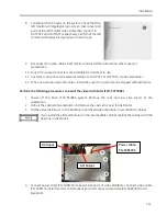
Functional check: Power on the system. Check that the
left monitor will display GE logo screen. Disconnect and
pull out the left monitor video cable then connect to
OUTPUT1 and OUTPUT2 respectively. Verify that the left
monitor will display GE logo screen in each case.
9.
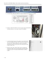
Reconnect the video cable of left monitor and install the cabinet and other covers of
workstation.
10.
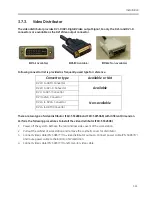
Only 2 DVI output connectors are available for customer to use.
11.
Customer can connect the external monitor to OUTPUT1 or OUTPUT2 of video distributor.
12.
When not use the external monitor, install the cover DVI port protector shipped with distributor.
Perform the following procedures to install the video distributor (FRU: 5075968).
1.
Power off the Brivo 715/785/865 system. Remove the rear and low side covers of the
workstation.
2.
Pull out the cabinet of workstation and remove the cosmetic cover for distributor.
3.
Put the video distributor on the backboard and fixed video distributor in workstation cabinet.
If you install the video distributor on the incompatible cabinet, replace the cabinet with the
new one in the FRU kit.
4.
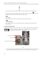
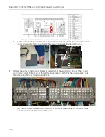
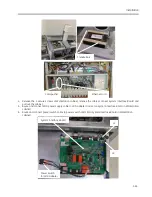
Connect power cable (PN: 5085793) to power input port of video distributor. Connect video cable
(PN: 5085733) of left monitor to DVI output port and connect video cable (PN: 5085792) to DVI
input port.
Power cable:
PN: 5085793
DVI Input
DVI Output
Содержание Brivo OEC 715
Страница 2: ......
Страница 19: ...Chapter1 Introduction and Safety...
Страница 41: ...Introduction and Safety 23 46 54 20 18 26...
Страница 55: ...Chapter2 System Overview...
Страница 137: ...Chapter3 Installation...
Страница 147: ...Installation 3 11 7 Put the ramp in position Release all bracket and move the workstation along the ramp off the pallet...
Страница 211: ...Installation 3 75 3 9 Reporting For U S Systems Complete and submit Form 2579 within 15 days of installation...
Страница 212: ...Chapter4 Calibration...
Страница 223: ...Brivo OEC 715 785 865 Mobile C Arm X Ray Product Service Manual 4 12 Mainframe Control Board TP7...
Страница 231: ...Brivo OEC 715 785 865 Mobile C Arm X Ray Product Service Manual 4 20 Mainframe Control Board TP17 POT4 J5 TP7 POT7 POT5...
Страница 275: ...Brivo OEC 715 785 865 Mobile C Arm X Ray Product Service Manual 4 64...
Страница 284: ...Chapter5 Software...
Страница 312: ...Software 5 29 4 Click Next 5 Click Install 6 Click Finish button to complete installation procedure...
Страница 326: ...Software 5 43 2 Click on install to continue 3 Click Next to continue...
Страница 335: ...Chapter6 Troubleshooting...
Страница 408: ...Chapter7 Replacement...
Страница 418: ...Replacement 7 11 166...
Страница 488: ...Chapter8 Periodic Maintenance...
Страница 502: ...Periodic Maintenance 8 15...
Страница 505: ...Chapter9 Technical Reference...
Страница 520: ...Brivo OEC 715 785 865 Mobile C Arm X Ray Product Service Manual 9 16 Lateral configuration 1 5m Lateral configuration 1m...
Страница 521: ...Technical Reference 9 17 Vertical configuration 1 5m Vertical configuration 1m...
Страница 526: ...11 Appendix System Schematics...

