Brivo OEC 715/785/865 Mobile C-Arm X-ray Product Service Manual
8-6
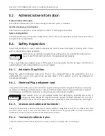
8.3.
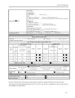
Administrative Information
Medical Facility Information:
Enter all information about the medical facility where the system is installed.
Field Service Engineer Information:
Enter Field Service Engineer name, Region ID number and Employee ID number.
System Configuration:
Complete each field in the System Configuration section. This section identifies specific information about
the system being maintained.
8.4.
Safety Inspection
Follow this procedure to inspect system components. Look for loose, damaged, or missing parts. Check
each component for proper operation.
Electrical circuits inside the equipment use voltages that are capable of causing serious
injury or death from electrical shock. Use appropriate precautions.
If the system has power applied, power off the system and unplug the C-Arm’s AC power cord from AC
outlet. Remove C-arm and workstation covers as needed.
8.4.1.
Antistatic Drag Wires
Check the system’s antistatic drag wires. There is one suspended below the workstation and one
underneath the C-Arm. Both wires must securely attach to the system and not be damaged or
encumbered by debris.
8.4.2.
Electrical Plug and power cord
Inspect the C-Arm’s AC power cord and AC line plug for damage and missing parts. Make sure all wiring
insulation is intact. Ensure that there are no broken or frayed wires. Make sure grounding pin is present
on AC line plug, and that all conductors on plug are secure and in good condition.
Some devices such as high voltage cables and electrolytic capacitors can retain a
dangerous static charge for long periods after power has been removed. Do not touch
these components unless power has been completely removed and they have discharged.
8.4.3.
Interconnect cable and Connector
Check the interconnect cable for damage or other problems. Verify that connector on cable mates well
with the connector on C-Arm and that there are no bent or missing pins. Make sure the strain relief
attaches securely to both the interconnect cable and connector.
8.4.4.
Footswitch cable and pins
Inspect footswitch cable and verify that the cable, connector and pins are not damaged.
WARNING
WARNING
Содержание Brivo OEC 715
Страница 2: ......
Страница 19: ...Chapter1 Introduction and Safety...
Страница 41: ...Introduction and Safety 23 46 54 20 18 26...
Страница 55: ...Chapter2 System Overview...
Страница 137: ...Chapter3 Installation...
Страница 147: ...Installation 3 11 7 Put the ramp in position Release all bracket and move the workstation along the ramp off the pallet...
Страница 211: ...Installation 3 75 3 9 Reporting For U S Systems Complete and submit Form 2579 within 15 days of installation...
Страница 212: ...Chapter4 Calibration...
Страница 223: ...Brivo OEC 715 785 865 Mobile C Arm X Ray Product Service Manual 4 12 Mainframe Control Board TP7...
Страница 231: ...Brivo OEC 715 785 865 Mobile C Arm X Ray Product Service Manual 4 20 Mainframe Control Board TP17 POT4 J5 TP7 POT7 POT5...
Страница 275: ...Brivo OEC 715 785 865 Mobile C Arm X Ray Product Service Manual 4 64...
Страница 284: ...Chapter5 Software...
Страница 312: ...Software 5 29 4 Click Next 5 Click Install 6 Click Finish button to complete installation procedure...
Страница 326: ...Software 5 43 2 Click on install to continue 3 Click Next to continue...
Страница 335: ...Chapter6 Troubleshooting...
Страница 408: ...Chapter7 Replacement...
Страница 418: ...Replacement 7 11 166...
Страница 488: ...Chapter8 Periodic Maintenance...
Страница 502: ...Periodic Maintenance 8 15...
Страница 505: ...Chapter9 Technical Reference...
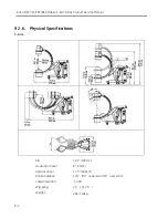
Страница 520: ...Brivo OEC 715 785 865 Mobile C Arm X Ray Product Service Manual 9 16 Lateral configuration 1 5m Lateral configuration 1m...
Страница 521: ...Technical Reference 9 17 Vertical configuration 1 5m Vertical configuration 1m...
Страница 526: ...11 Appendix System Schematics...

