Installation and Operation Guide
ED-DT318B
Drive Train Systems with Traction Control, Inverter/Controller, and Motor with 2 Speed Transmission
BC353060341319en-000101
Revision D
© Danfoss | November 2020 | 47
Classified as Business
The coolant for the Danfoss Power Solutions system must be designed and specified by the user or vehicle
integrator. The heat rejection for the system is dependent upon the drive cycle; therefore, the customer must
size the coolant system based on the drive cycle power requirements in the application. The losses can be
determined from the efficiency maps for the propulsion system.
The motor and controller coolant fittings are attached to the respective devices via an O-ring port specified by
SAE J1926-10. The controller and motor have 90
°
elbows that adapt to the hoses and rotate to meet with the
particular application. The coolant fittings can be unscrewed and changed to meet the requirements of the
application. Many different fittings are available that fit the SAE J1926-10 O-ring boss.
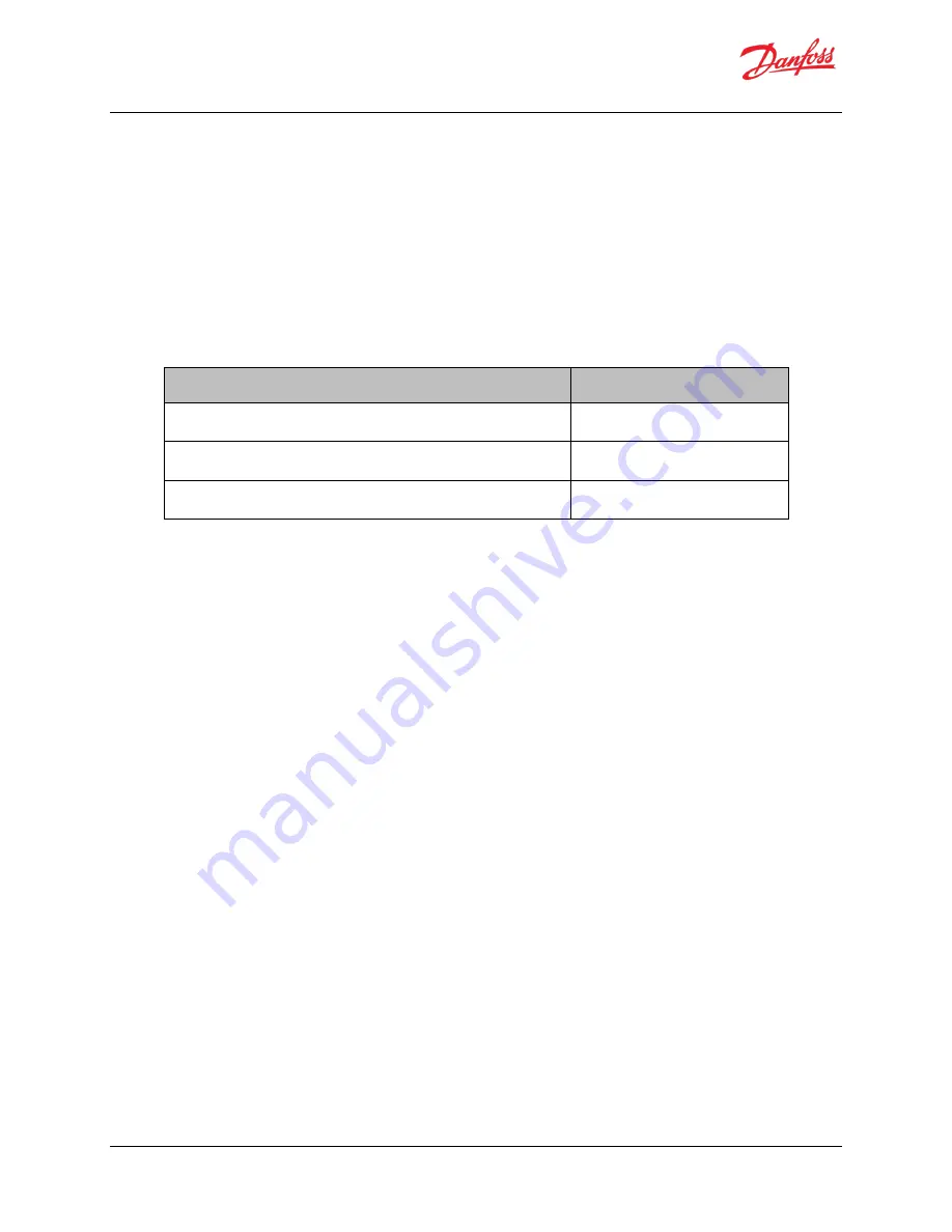
For proper performance and to achieve rated power, the coolant loop must meet the following requirements:
Table 4.1: Liquid Cooling System Requirements
Requirement
Specification
Coolant Type
50/50 water to glycol
Maximum Inlet Coolant Temperature (full performance)
60
°
C
Minimum Coolant Flow Rate
10 liters per minute (LPM)
Coolant volume for the controller and motor can be found on the ICD drawing or by contacting Danfoss Power
Solutions.
A coolant flow rate of 10.0 liters per minute will have a pressure drop of approximately 8.5 kPa total from just the
controller and motor. This does not include additional fittings, valves, or plumbing.
Note in
that the coolant should go from the radiator, through the pump, and on to the controller.
Then, it should move from the controller, to the motor, and back to the radiator. The controller is more heat
sensitive than the motor and needs the coolant to be as cool as possible. While the system can operate at
maximum rated coolant temperatures, the operating life of the controller will be extended if the coolant is kept
below the maximum operating temperature.
To make loading the coolant into the system easier, make sure the radiator fill port is higher than the motor and
controller, which allows air to flow out of the coolant system more easily.
4.2
Flow Rate vs. Pressure Drop
The total pressure drop in the system is the summation of the pressure drop across the controller, motor, and all
customer installed hosing and fittings. The flow rate data is included on the ICD drawings.
Содержание ED-DT318B
Страница 185: ......


