


Installation and Operation Guide
ED-DT318B
Drive Train Systems with Traction Control, Inverter/Controller, and Motor with 2 Speed Transmission
BC353060341319en-000101
Revision D
© Danfoss | November 2020 | 43
Classified as Business
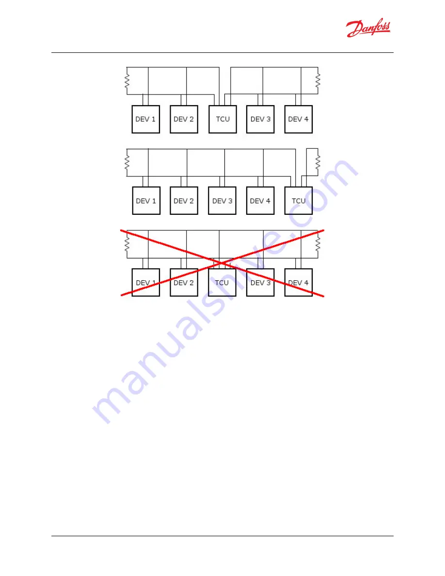
Figure 3.12: Allowed VCU to TCU CAN Bus Configurations
3.6
DT2 Diagnostic Connector
The DT2 Diagnostic Connector (Connector 4 in
) provides diagnostic access to the VCU to TCU CAN
bus, the TCU to MCU CAN bus, and the MCU RS232 diagnostic bus for the Motor Diagnostic Software (
Section 8
Access to the VCU to TCU CAN buss allows the messages being passed on that but to be monitored and
correlated to system activity.
Access to the TCU and MCU CAN bus allows monitoring of communications between the TCU and MCU. It also
used to update TCU and MCU firmware and TCU configuration data. The MCU configuration is updated via the
RS232 port documented below.
Danfoss Power Solutions provides one TCU to MCU CAN bus termination resistor, which is located within the
body of the Danfoss Power Solutions inverter. The customer is responsible for the second termination resistor,
which should be located at Diagnostic Connector. See
for the recommended layout of the TCU to
MCU CAN bus. Note that the wiring from the MCU to the TCU is provided by Danfoss Power Solutions via the
TCU to MCU Interface Cable. The customer is responsible for the wiring from the Drivetrain Interface Connector
to the Diagnostic Connector.
The Danfoss Power Solutions Motor Diagnostic Software (
Section
) communicates to the motor system through
the RS232 communication pins (7, 15 & 8) of the Diagnostic Connector.
Communications with the MCU conforms to the RS232 signal protocol. When wiring from the Diagnostic
Connector to a 9pin D connector, the user must ensure that the pin assignments in
are followed.
Содержание ED-DT318B
Страница 185: ......


