ZyXEL Communications XS3800-28 User Manual Download Page 679

 Chapter 87 MAINTENANCE

XS3800-28 User’s Guide

679

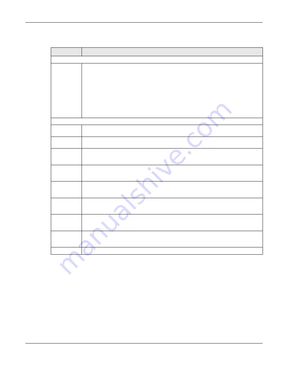
The following table describes the labels in this screen.

87.14  Diagnostic

Click 

MAINTENANCE

 >

 Diagnostic 

in the navigation panel to open this screen. Use this screen to ping IP 

addresses, run a traceroute, perform port tests or show the Switch’s location between devices.

Table 365   MAINTENANCE > Configuration > Configure Clone

LABEL

DESCRIPTION

Configure Clone

Source/
Destination

In Stacking mode, a port is defined by a slot ID representing the Switch in the stack and a port 
number.

Select the source port and slot (in Stacking mode) under the 

Source

 label. This port’s attributes are 

copied.

Enter the destination port or ports under the 

Destination

 label. These are the ports which are going 

to have the same attributes as the source port. You can enter individual ports separated by a 
comma or a range of ports by using a hyphen. For example, 

2, 4, 6

 indicates that ports 2, 4 and 6 

are the destination ports. 

2-6

 indicates that ports 2 through 6 are the destination ports.

In Stacking mode, you can select multiple destination slots.

Port Features

Port

Select * to apply all settings to the port. Use this first to select the common settings and then 
remove the settings you do not want copied.

Select a feature’s check box to select a specific feature. Otherwise, select the check box in the 
table heading row to select all features for a category.

SYSTEM

Select the system feature (you configured in the 

SYSTEM

 menus) to be copied to the destination 

ports. Otherwise, select the 

SYSTEM 

check box in the table heading row to select all features for a 

category.

PORT

Select which port features (you configured in the 

PORT

 menus) should be copied to the 

destination ports. Otherwise, select the 

PORT 

check box in the table heading row to select all 

features for a category.

SWITCHING

Select which switching features (you configured in the 

SWITCHING

 menus) should be copied to 

the destination ports. Otherwise, select the 

SWITCHING 

check box in the table heading row to 

select all features for a category.

NETWORKING

Select the networking feature (you configured in the 

NETWORKING

 menus) to be copied to the 

destination ports. Otherwise, select the 

NETWORKING 

check box in the table heading row to 

select all features for a category.

SECURITY

Select which security features (you configured in the 

SECURITY

 menus) should be copied to the 

destination ports. Otherwise, select the 

SECURITY 

check box in the table heading row to select all 

features for a category.

Apply

Click 

Apply

 to save your changes to the Switch’s run-time memory. The Switch loses these 

changes if it is turned off or loses power, so use the 

Save

 link on the top navigation panel to save 

your changes to the non-volatile memory when you are done configuring.

Cancel

Click 

Cancel

 to begin configuring this screen afresh.

Summary of Contents for XS3800-28

Page 1: ...E L3 Managed Switch Copyright 2022 Zyxel and or its affiliates All Rights Reserved Out of Band MGMT Port http 192 168 0 1 In Band Ports http setup zyxel or http DHCP assigned IP or http 192 168 1 1 Us...

Page 2: ...the Switch Web Configurator Online Help Click the Help icon in any screen for help in configuring that screen and supplementary information Networked AV Mode Online Help Click the Help icon in Networ...

Page 3: ...Product labels screen names field labels and field choices are all in bold font A right angle bracket within a screen name denotes a mouse click For example SYSTEM IP Setup Network Proxy Configuratio...

Page 4: ...RD 105 MONITOR 111 ARP Table 112 IP Table 114 IPv6 Neighbor Table 116 MAC Table 118 Neighbor 121 Path MTU Table 126 Routing Table 136 System Information 138 System Log 144 SYSTEM 146 Cloud Management...

Page 5: ...Queuing Method 362 Priority Queue 366 Bandwidth Control 368 sFlow 371 Spanning Tree Protocol 375 Static MAC Filtering 407 Static MAC Forwarding 409 VLAN 412 VLAN Isolation 441 VLAN Mapping 444 VLAN S...

Page 6: ...Guide 6 Storm Control 593 Error Disable 596 IP Source Guard 604 DHCP Snooping 609 ARP Inspection 621 Port Authentication 642 Port Security 657 MAINTENANCE 663 Networked AV Mode 691 Troubleshooting and...

Page 7: ...2 1 Backbone Example Application 36 1 2 2 Bridging or Fiber Optic Uplink Example Application 37 1 2 3 High Performance Switching Example 38 1 2 4 IEEE 802 1Q VLAN Application Examples 38 1 2 5 IPv6 S...

Page 8: ...erview 55 4 2 System Login 55 4 3 Zyxel One Network ZON Utility 60 4 3 1 Requirements 60 4 3 2 Run the ZON Utility 60 4 4 Networked AV Mode Wizard 64 4 4 1 Basic Settings 64 4 4 2 Advanced Settings 69...

Page 9: ...a DHCP Server on the Switch 101 Chapter 7 DASHBOARD 105 7 1 New User Interface 105 7 2 DASHBOARD 105 7 2 1 Port Status 109 7 2 2 Quick Links to Use 109 Chapter 8 MONITOR 111 Chapter 9 ARP Table 112 9...

Page 10: ...126 Chapter 15 15 0 1 What You Can Do 127 15 1 Port Status 127 15 1 1 Port Details 129 15 2 DDMI 131 15 2 1 DDMI Details 132 15 3 Port Utilization 134 Chapter 16 Routing Table 136 16 1 Routing Table O...

Page 11: ...rfaces 157 23 2 IP Status 158 23 2 1 IP Status Details 158 23 3 IP Setup 160 23 3 1 Add Edit IP Interfaces 162 23 4 Network Proxy Configuration 163 Chapter 24 IPv6 165 24 1 IPv6 Overview 165 24 1 1 Wh...

Page 12: ...re SNMP 184 26 3 Configure SNMP User 186 26 3 1 Add Edit SNMP User 186 26 4 Configure SNMP Trap Group 188 26 5 Enable or Disable Sending of SNMP Traps on a Port 189 26 6 Technical Reference 191 26 6 1...

Page 13: ...it Flex Link 218 Chapter 33 Green Ethernet 220 33 1 Green Ethernet Overview 220 33 2 Configuring Green Ethernet 220 Chapter 34 Link Aggregation 224 34 1 Link Aggregation Overview 224 34 1 1 What You C...

Page 14: ...MED Location 256 Chapter 36 OAM 260 36 1 OAM Overview 260 36 1 1 What You Can Do 260 36 2 OAM Status 260 36 2 1 OAM Details 262 36 3 OAM Setup 266 36 4 OAM Remote Loopback 268 Chapter 37 Port Setup 2...

Page 15: ...Source 296 43 4 1 Add Edit Source 297 43 5 Destination 299 43 5 1 Add Edit Destination 300 43 6 Connected Port 301 43 6 1 Add Edit Connected Ports 301 Chapter 44 Multicast 304 44 1 Multicast Overview...

Page 16: ...45 1 Static Multicast Forwarding Overview 335 45 1 1 What You Can Do 335 45 1 2 What You Need To Know 335 45 2 Static Multicast Forwarding By MAC 336 45 2 1 Add Edit Static Multicast Forwarding By MA...

Page 17: ...hat You Need to Know 362 50 2 Configuring Queuing 363 Chapter 51 Priority Queue 366 51 1 Priority Queue Overview 366 51 1 1 What You Can Do 366 51 2 Assign Priority Queue 366 Chapter 52 Bandwidth Cont...

Page 18: ...3 MST Instance 405 54 11 4 Common and Internal Spanning Tree CIST 405 Chapter 55 Static MAC Filtering 407 55 1 Static MAC Filtering Overview 407 55 1 1 What You Can Do 407 55 2 Configure a Static MAC...

Page 19: ...ure a Port Based VLAN 438 Chapter 58 VLAN Isolation 441 58 1 VLAN Isolation Overview 441 58 2 Configuring VLAN Isolation 441 58 2 1 Add Edit a VLAN Isolation Rule 442 Chapter 59 VLAN Mapping 444 59 1...

Page 20: ...ption 82 Profile 470 64 4 1 Add Edit a DHCPv4 Option 82 Profile 471 64 5 Configuring DHCPv4 Smart Relay 472 64 5 1 Add Edit DHCPv4 Global Relay Port 473 64 5 2 DHCP Smart Relay Configuration Example 4...

Page 21: ...Chapter 67 OSPF 501 67 1 OSPF Overview 501 67 1 1 OSPF Autonomous Systems and Areas 501 67 1 2 How OSPF Works 502 67 1 3 Interfaces and Virtual Links 502 67 1 4 OSPF and Router Elections 502 67 1 5 C...

Page 22: ...Routing Overview 526 71 1 1 What You Can Do 526 71 2 IPv4 Static Route 527 71 2 1 Add Edit IPv4 Static Route 527 71 3 IPv6 Static Route 528 71 3 1 Add Edit IPv6 Static Route 529 Chapter 72 VRRP 531 7...

Page 23: ...75 3 Remote Management 557 75 4 Account Security 558 75 5 Technical Reference 560 75 5 1 SSH Overview 560 75 5 2 Introduction to HTTPS 562 75 5 3 Google Chrome Warning Messages 564 Chapter 76 Classif...

Page 24: ...0 Chapter 80 Storm Control 593 80 1 Storm Control Overview 593 80 1 1 What You Can Do 593 80 2 Storm Control Setup 593 Chapter 81 Error Disable 596 81 1 Error Disable Overview 596 81 1 1 CPU Protectio...

Page 25: ...Inspection Port Setup 625 84 6 ARP Inspection VLAN Setup 627 84 7 IPv6 Source Guard 628 84 8 IPv6 Source Binding Status 628 84 9 IPv6 Static Binding 629 84 9 1 Add Edit IPv6 Static Binding 630 84 10...

Page 26: ...1 Overview 663 87 1 1 What You Can Do 663 87 2 Certificates 663 87 2 1 HTTPS Certificates 665 87 3 Technical Reference 665 87 3 1 FTP Command Line 665 87 3 2 Filename Conventions 666 87 3 3 FTP Comma...

Page 27: ...4 88 14 Configure SNMP User 706 88 14 1 Add Edit SNMP User 707 88 15 Configure SNMP Trap Group 708 88 16 Enable or Disable Sending of SNMP Traps on a Port 709 88 17 PORT 710 88 18 Link Aggregation 711...

Page 28: ...ent 739 88 38 Storm Control 740 88 39 MAINTENANCE 741 88 40 What You Can Do 742 88 41 Restore Configuration 742 88 42 Backup Configuration 742 88 43 Save Configuration 743 88 44 Firmware Upgrade 744 8...

Page 29: ...29 PART I User s Guide...

Page 30: ...P slots for fiber connections to the backbone switches and you could use the 10 Gbps Ethernet ports for connections to other Ethernet devices requiring high bandwidth such as network attached storage...

Page 31: ...0 m is used The speed drops to 1G if these criteria are not met it drops to 100M if a Cat 5 cable is used up to 100 m If a network device such as a 5G network card gaming computer server Network Attac...

Page 32: ...onding speed Note Make sure to select the correct speed for the port in PORT Port Setup 1 1 3 Stacking Mode The Switch can work in Stacking mode and directly connect to other switches The switches the...

Page 33: ...t the Nebula web portal at https nebula zyxel com and ensure that Nebula Control Center NCC Discovery is enabled in SYSTEM Cloud Management in the Switch Web Configurator Note See the Switch s datashe...

Page 34: ...Start on the first page Click Create account to create a myZyxel account or enter your existing account information to log in 2 Create an organization and site or select an existing site using the Zyx...

Page 35: ...program called Zyxel One Network ZON Utility it is a utility tool that assists you to set up and maintain network devices in a more simple and efficient way You can download the ZON Utility at www zy...

Page 36: ...tworked AV mode s basic and advanced settings Figure 4 Comparison Between Traditional AV and AVoIP Setups 1 2 Example Applications This section shows a few examples of using the Switch in various netw...

Page 37: ...viate bandwidth contention and eliminate server and network bottlenecks All users that need high bandwidth can connect to high speed department servers through the Switch You can provide a super fast...

Page 38: ...4 IEEE 802 1Q VLAN Application Examples A VLAN Virtual Local Area Network allows a physical network to be partitioned into multiple logical networks Stations on a logical network belong to one or mor...

Page 39: ...oping and proxy For more information on IPv6 refer to Appendix C on page 760 and the CLI Reference Guide 1 3 Ways to Manage the Switch Use any of the following methods to manage the Switch NCC Zyxel N...

Page 40: ...ecure and to manage the Switch more effectively Change the password Use a password that is not easy to guess and that consists of different types of characters such as numbers and letters Write down t...

Page 41: ...and at least 5 cm of clearance on all four sides of the Switch This allows air circulation for cooling Do NOT block the ventilation holes nor store cables or power cords on the Switch Allow clearance...

Page 42: ...for air circulation 2 4 Mounting the Switch on a Rack The Switch can be mounted on an EIA standard size 19 inch rack or in a wiring closet with other equipment Follow the steps below to mount your Sw...

Page 43: ...s through the mounting bracket holes into the Switch 3 Repeat steps 1 and 2 to install the second mounting bracket on the other side of the Switch 4 You may now mount the Switch on a rack Proceed to t...

Page 44: ...and Connection XS3800 28 User s Guide 44 the rack Note Make sure you tighten all the four screws to prevent the Switch from getting slanted 3 Repeat steps 1 and 2 to attach the second mounting bracke...

Page 45: ...e ports for high bandwidth backbone connections You can also insert an SFP Direct Attach Copper DAC in the SFP slot 4 100 Mbps 1 Gbps 2 5 Gbps 5 Gbps and 10 Gbps RJ 45 Ethernet Ports These are 10GBase...

Page 46: ...r the Ethernet ports on the Switch are Speed Auto Duplex Auto Flow control Off Dual Personality Interface Fiber optic module first 3 1 2 SFP SFP Slots The transceiver slots are for Small Form Factor P...

Page 47: ...Installation Use the following steps to install a transceiver 1 Attach an ESD preventive wrist strap to your wrist and to a bare metal surface 2 Align the transceiver in front of the slot opening 3 M...

Page 48: ...can be pulled out successfully 4 Pull the latch or use your thumb and index finger to grasp the tabs on both sides of the transceiver and carefully slide it out of the slot Note Do NOT pull the transc...

Page 49: ...Ethernet MGMT management port is used for local management Connect directly to this port using an Ethernet cable You can configure the Switch through Telnet or the Web Configurator The default IP add...

Page 50: ...r enclosed conduit for protecting electric wiring that is 15 cm apart or as specified by your country s electrical regulations Any device that is located outdoors and connected to this product must be...

Page 51: ...inspection authority or an electrician This device must be grounded Do this before you make other connections 3 2 2 AC Power Connection Note Make sure you are using the correct power source as shown o...

Page 52: ...urce The fans are not functioning at a proper speed or malfunctioning Off The Switch is not receiving power from the power module in the first power slot PWR2 Green On The Switch is receiving power fr...

Page 53: ...mode Amber On There is an error occurred when the Switch is selected as the master member in a stack Ethernet Ports 17 28 Green On The port has a successful 100 Mbps 1 Gbps 2 5 Gbps 5 Gbps connection...

Page 54: ...54 PART II Technical Reference...

Page 55: ...ult Type http DHCP assigned IP in the Location or Address field Press ENTER Note You can always use the domain name setup zyxel to access the Web Configurator whether the Switch is using a DHCP assign...

Page 56: ...The NCC is a cloud based network management system that allows you to remotely manage and monitor the Switch See Section 1 1 5 on page 33 for information on changing your Switch to Nebula Cloud manage...

Page 57: ...sic or advanced settings see Section 4 4 on page 64 for details Use the Basic Settings to configure networked AV operation on management VLAN Such as the Switches IP address DNS server system password...

Page 58: ...Mode Click Password SNMP to open a screen where you can change the administrator password and SNMP community string simultaneously Otherwise click Ignore to close it If you log into the Web Configura...

Page 59: ...sion on the Switch must match the version on the SNMP manager Choose SNMP version 2c v2c SNMP version 3 v3 or both v3v2c Note SNMP version 2c is backwards compatible with SNMP version 1 Get Community...

Page 60: ...install it in a computer Windows operating system 4 3 1 Requirements Before installing the ZON Utility in your computer please make sure it meets the requirements listed below Operating System At the...

Page 61: ...Show information about ZON icon in the upper right of the screen Then select the Supported model and firmware version link If your device is not listed here see the device release notes for ZON Utili...

Page 62: ...es in your network Figure 33 Discovery 5 The ZON Utility screen shows the devices discovered Figure 34 ZON Utility Screen 6 Select a device and then use the icons to perform actions Some functions may...

Page 63: ...nzipped it in advance 8 Change Password Use this icon to change the admin password of the selected device You must know the current admin password before changing to a new one 9 Configure NCC Discover...

Page 64: ...s of an internal interface on the discovered device that first received a ZDP discovery request from the ZON Utility System Name This field displays the system name of the discovered device Location T...

Page 65: ...c IP Interface when the Switch is NOT connected to a router or you want to assign it a fixed IP address VID This field displays the VLAN ID IP Address The Switch needs an IP address for it to be manag...

Page 66: ...Enabled to let the Switch act as an SNMP agent which allows a manager station to manage and monitor the Switch through the network Select Disabled to turn this feature off Version Select the SNMP ver...

Page 67: ...2 Wizard Basic Settings Step 3 Networked AV LABEL DESCRIPTION Skip Networked AV Mode Settings Click this option to avoid using the basic default AVoIP settings The default AVoIP settings can be seen i...

Page 68: ...ress Default Gateway This field displays the IP address of the default outgoing gateway in dotted decimal notation for example 192 168 1 254 DNS Server This field displays the DNS Domain Name System f...

Page 69: ...P Snooping Querier This field displays Active when the Switch is allowed to send IGMP General Query messages to the VLANs with the multicast hosts attached Otherwise it displays Inactive Unknown Multi...

Page 70: ...s the Switch s Web Configurator again Select Static IP Interface when the Switch is NOT connected to a router or you want to assign it a fixed IP address VID This field displays the VLAN ID IP Address...

Page 71: ...ct Enabled to let the Switch act as an SNMP agent which allows a manager station to manage and monitor the Switch through the network Select Disabled to turn this feature off Version Select the SNMP v...

Page 72: ...Table 16 Wizard Advanced Settings Step 3 Networked AV LABEL DESCRIPTION Allocate networked AV service to a VLAN Networked AV VLAN Enter a number between 1 and 4094 to create a VLAN for the AVoIP netwo...

Page 73: ...k Management to assign the ports for connecting to non Audio Video equipment for example computer and NAS Link aggregate Select this option to aggregate multiple port bandwidth if you are connecting t...

Page 74: ...his field displays the Trap Community string Networked AV Advanced Settings Networked AV VLAN This field displays the VLAN ID for the AVoIP network Networked AV VLAN IP This field displays the corresp...

Page 75: ...mation in the screen you are currently viewing G Click this icon to save your configuration into the Switch s non volatile memory Non volatile memory is the configuration of your Switch that stays the...

Page 76: ...kes you to a screen where you can view the IPv4 routing table for routing information including IP interface and hop count to certain network destinations IPv6 Routing Table This link takes you to a s...

Page 77: ...arameters such as VLAN type Syslog Setup This link takes you to a screen where you can configure the Switch s system logging settings and configure a list of external syslog servers Time Range This li...

Page 78: ...col over Ethernet Intermediate Agent and configure per port per port per VLAN settings Private VLAN This link takes you to a screen where you can block traffic between ports in a VLAN on the Switch Qo...

Page 79: ...VLANs based on the source MAC address of the packet You can specify a mask for the MAC address to create a MAC address filter and enter a weight to set the VLAN rule s priority VLAN Isolation This li...

Page 80: ...CS Server Setup This link takes you to a screen where you can configure your TACACS Terminal Access Control ler Access Control System Plus server settings for authentication AAA Setup This link takes...

Page 81: ...ted for DHCPv6 snoop ing Port Authenti cation Click the link to unfold the following sub link menu These links take you to screens where you can configure IEEE 802 1x port authentication as well as MA...

Page 82: ...Control status and Networked AV status MONITOR System Information This link takes you to a screen that displays general system information SYSTEM General Setup This link takes you to a screen where y...

Page 83: ...s you to a screen where you can specify a group of one or more trusted computers from which an administrator may use a service to manage the Switch Storm Control This link takes you to a screen to set...

Page 84: ...t administrator password Click SYSTEM Logins to display the next screen Table 20 Common Table Icons LABEL DESCRIPTION Select an entry s check box to select a specific entry Otherwise select the check...

Page 85: ...ave your configuration to non volatile memory Non volatile memory refers to the Switch s storage that remains even if the Switch s power is turned off Note Use the Save link when you are done with a c...

Page 86: ...ee Section 3 3 on page 52 for more information about the LED behavior 4 8 2 Reload the Configuration File Uploading the factory default configuration file replaces the current configuration file with...

Page 87: ...ish a management session for security reasons Figure 50 Logout button 4 10 Help The Web Configurator s online help has descriptions of individual screens and some supplementary information Click the H...

Page 88: ...Chapter 4 Web Configurator XS3800 28 User s Guide 88 Figure 51 Online Web Help...

Page 89: ...tup Create a VLAN Set Port VID Configure Switch Management IP Address 5 1 1 Create a VLAN VLANs confine broadcast frames to the VLAN group in which the ports belongs You can do this with port based VL...

Page 90: ...configure port 1 to be a permanent member of the VLAN only 4 To ensure that VLAN unaware devices such as computers and hubs can receive frames properly clear the Tx Tagging check box to set the Switc...

Page 91: ...ly to save your changes back to the run time memory Settings in the run time memory are lost when the Switch s power is turned off 5 1 3 Configure Switch Management IP Address If the Switch fails to o...

Page 92: ...nd enter setup zyxel or 192 168 1 1 the default IP address in the address bar to access the Web Configurator See Section 4 2 on page 55 for more information Note You can always use the domain name set...

Page 93: ...k 5 In the VID field enter the ID of the VLAN group to which you want this management IP address to belong In this example enter VLAN ID 2 This is the same as the VLAN ID you configure in the Static V...

Page 94: ...network V Create a VLAN containing ports 4 5 and 6 Connect a computer M to the Switch for management Figure 55 Tutorial DHCP Snooping Tutorial Overview The settings in this tutorial are as the followi...

Page 95: ...Create a VLAN with ID of 100 Add ports 4 5 and 6 in the VLAN by selecting Fixed in the Control field as shown De select Tx Tagging because you do not want outgoing traffic to contain this VLAN tag Cl...

Page 96: ...IPv4 Source Guard DHCP Snooping DHCP Snp VLAN Setup screen will be broadcast to the DHCP VLAN you set on this screen which is VLAN100 in this example Tutorial Specify DHCP VLAN 6 Go to SECURITY IPv4 S...

Page 97: ...name you can select an Option82 Profile in the entry The Switch will add DHCP option 82 information to DHCP requests that the Switch relays to a DHCP server for the specified VLAN 8 Connect your DHCP...

Page 98: ...P server 192 168 2 3 and want to have it assign a specific IP address say 172 16 1 18 to DHCP client A based on the system name VLAN ID and port number in the DHCP request Client A connects to the Swi...

Page 99: ...lick Add Edit 4 The following screen appears Enable the switch button to set this VLAN to Active Enter a descriptive name VLAN 102 for example in the Name field and enter 102 in the VLAN Group ID fiel...

Page 100: ...tag to incoming untagged frames received on that port so that the frames are forwarded to the VLAN group that the tag defines 9 Click Apply to save your changes back to the run time memory 10 Click t...

Page 101: ...e sure 1 Client A is connected to the Switch s port 2 in VLAN 102 2 You configured the correct VLAN ID port number and system name for DHCP relay on both the DHCP server and the Switch 3 You clicked t...

Page 102: ...DHCP option 60 enabled and a Vendor Class Identifier assigned when you reboot the Switch follow the instruction below Otherwise skip this step Enter the filename of an auto configuration file Set up a...

Page 103: ...s Identifier in the Class ID field and specify the VLAN interface in the VID field In this example we use ZyxelCorp and VID 1 Click Apply Figure 59 Tutorial Enable DHCP Client Option 60 6 You need to...

Page 104: ...ONITOR System Log screen to see if auto configuration was performed successfully Figure 62 Tutorial Log 9 Check the screens to see if it is the configuration file you want to load If it is not go thro...

Page 105: ...e circles Clickable hardware status monitoring sections that directly link to the MONITOR System Information screen Editable Quick Link section which provides shortcuts to configuration screens that y...

Page 106: ...cally refreshes every 30 seconds Click this to disable the auto refresh Click Resume Auto Refresh to enable Port Status This displays individual port type status and connection speed of the Switch Cli...

Page 107: ...mber and date of the firmware the Switch is currently running System Time This field displays the current date and time in the UAG The format is mm dd yyyy hh mm ss System Uptime This field displays h...

Page 108: ...on NCC Gray The Switch is not registered on NCC Note All circles will gray out if you disable Nebula Discovery Note If a circle displays orange or gray hover the mouse over the circle to check the di...

Page 109: ...ks in the Quick Link section provide shortcuts to specific configuration screens You can use the quick links to directly access the screens that you would frequently use You can also decide which quic...

Page 110: ...gure 67 Quick Links The setup panel displays after you click the Edit button Figure 68 Quick Link Selection Select the quick links you want and click Apply The selected quick links will be displayed i...

Page 111: ...ers introduces the configurations of the links under the MONITOR navigation panel Quick links to chapters ARP Table IP Table IPv6 Neighbor Table MAC Table Neighbor Path MTU Table Port StatusThis chapt...

Page 112: ...Table and if it finds the address it sends it to the device If no entry is found for the IP address ARP broadcasts the request to all the devices on the LAN The Switch fills in its own MAC and IP add...

Page 113: ...the condition you specified Cancel Click Cancel to return the fields to the factory defaults Index This is the ARP table entry number IP Address This is the IP address of a device connected to a Swit...

Page 114: ...re 1 The Switch examines a received packet and learns the port from which this source IP address came 2 The Switch checks to see if the packet s destination IP address matches a source IP address alre...

Page 115: ...hich the above IP address was learned This field displays CPU to indicate the IP address belongs to the Switch In stacking mode the first number represents the slot and the second the port number Type...

Page 116: ...Pv6 Neighbor Setup screen When the Switch needs to send a packet it first consults other table to determine the next hop Once the next hop IPv6 address is known the Switch looks into the neighbor tabl...

Page 117: ...pper layer protocols a chance to determine reachability probe P The Switch is sending request packets and waiting for the neighbor s response invalid IV The neighbor address is with an invalid IPv6 ad...

Page 118: ...dynamic or static 12 1 2 What You Need to Know The Switch uses the MAC Table to determine how to forward frames See the following figure 1 The Switch examines a received frame and learns the port on...

Page 119: ...e Use this screen to search specific MAC addresses You can also directly add dynamic MAC addresses into the static MAC forwarding table or MAC filtering table from the MAC table using this screen Clic...

Page 120: ...nge the data according to port number Type Transfer Select Dynamic to MAC forwarding and click the Transfer button to change all dynamically learned MAC address entries in the summary table below into...

Page 121: ...hboring devices like login This screen shows the neighboring device first recognized on an Ethernet port of the Switch Device information is displayed in gray when the neighboring device is offline 13...

Page 122: ...slot number of the Switch in a stack Port This shows the port of the Switch on which the neighboring device is discovered In Stacking mode the first number represents the slot ID and the second is the...

Page 123: ...Chapter 13 Neighbor XS3800 28 User s Guide 123 Figure 77 MONITOR Neighbor Neighbor Details Standalone Mode...

Page 124: ...nts the slot and the second the port number Enter 1 1 1 24 2 23 for ports 1 to 24 for the Switch in slot 1 and port 23 for the Switch in slot 2 for example SLOT This field appears only in Stacking mod...

Page 125: ...do not support the ZON utility Desc This shows the description of the neighbor device s port which is connected to the Switch IPv4 This shows the IPv4 address of the neighbor device The IPv4 address...

Page 126: ...ble Use this screen to view IPv6 path MTU information on the Switch Click MONITOR Path MTU Table in the navigation panel to display the screen as shown Figure 79 MONITOR Path MTU Table The following t...

Page 127: ...FP transceivers on the Switch Use the Port Utilization screen Section 15 3 on page 134 to view the current data rate and utilization percentage of each port on the Switch 15 1 Port Status This screen...

Page 128: ...Down if the port is not connected to any device State If STP Spanning Tree Protocol is enabled this field displays the STP state of the port If STP is disabled this field displays FORWARDING if the li...

Page 129: ...led performance data about an individual port on the Switch Figure 82 MONITOR Port Status Port Details The following table describes the labels in this screen Table 31 MONITOR Port Status Port Details...

Page 130: ...nformation about packets transmitted Unicast This field shows the number of good unicast packets transmitted Multicast This field shows the number of good multicast packets transmitted Broadcast This...

Page 131: ...ackets received with a length that was out of range Runt This field shows the number of packets received that were too short shorter than 64 octets including the ones with CRC errors Distribution 64 T...

Page 132: ...own list to choose the slot number of the Switch in a stack Port This identifies the SFP port In Stacking mode the first number represents the slot ID and the second is the port number Please note tha...

Page 133: ...Revision This displays the revision number of the optical transceiver Date Code This displays the date when the optical transceiver was manufactured Transceiver This displays details about the type o...

Page 134: ...rom the fiber cable Current This displays the current status for each monitored DDMI parameter High Alarm Threshold This displays the high value alarm threshold for each monitored DDMI parameter An al...

Page 135: ...d They are reserved for stacking only Link This field displays the speed either 100M for 100Mbps 1G for 1 Gbps 2 5G for 2 5 Gbps 5G for 5 Gbps or 10G for 10 Gbps and the duplex F for full duplex or H...

Page 136: ...information Use the IPv6 Routing Table screen Section 16 3 on page 137 to view the Switch s IPv6 routing table information 16 2 IPv4 Routing Table Use this screen to view IPv4 routing table informatio...

Page 137: ...ays how long the route has been running since the Switch learned the route and added an entry in the routing table Table 35 MONITOR Routing Table IPv4 Routing Table continued LABEL DESCRIPTION Table 3...

Page 138: ...138 to view general system information and hardware status of the Switch Use the Hardware Monitor screen Section 17 2 on page 142 to monitor and check the hardware status of the Switch in Stacking mod...

Page 139: ...Chapter 17 System Information XS3800 28 User s Guide 139 Figure 90 MONITOR System Information Standalone Mode...

Page 140: ...f the Switch CPU Utilization Current This displays the current percentage of CPU utilization Memory Utilization Memory utilization shows how much DRAM memory is available and in use It also displays t...

Page 141: ...le of detecting and reporting if the voltage falls out of the tolerance range Status Normal indicates that the voltage is within an acceptable operating range at this point otherwise Error is displaye...

Page 142: ...when the Switch is in Stacking mode In the MONITOR System Information screen click an index of a Slot under Hardware Monitor to display the screen as shown Use this screen to view hardware information...

Page 143: ...t this fan is functioning above the minimum speed Error indicates that this fan is functioning below the minimum speed Current This field displays this fan s current speed in Revolutions Per Minute RP...

Page 144: ...n for viewing 18 2 System Log Click MONITOR System Log in the navigation panel to open this screen Use this screen to check current system logs Note When a log reaches the maximum number of log messag...

Page 145: ...e shows the time the log message was recorded and the reason the log message was generated Click Refresh to update this screen Click Clear to clear the whole log regardless of what is currently displa...

Page 146: ...ing chapters introduces the configurations of the links under the SYSTEM navigation panel Quick links to chapters Cloud Management General Setup Hardware Monitor Setup Interface Setup IP Setup IPv6 Lo...

Page 147: ...ows you to remotely manage and monitor Zyxel Nebula APs Ethernet switches and security gateways The Switch is managed and provisioned automatically by the NCC Nebula Control Center when It is connecte...

Page 148: ...Chapter 20 Cloud Management XS3800 28 User s Guide 148 Figure 94 SYSTEM Cloud Management...

Page 149: ...e app to scan the QR code to register the Switch on NCC and add the Switch into a site Table 39 SYSTEM Cloud Management LABEL DESCRIPTION Nebula Control Center NCC Discovery Enable the switch button t...

Page 150: ...Chapter 20 Cloud Management XS3800 28 User s Guide 150 If Nebula Control Center NCC Discovery is disabled the Switch will NOT discover the NCC and remain in Standalone mode...

Page 151: ...95 SYSTEM General Setup Note The input string of any field in this screen should not contain or The following table describes the labels in this screen Table 40 SYSTEM General Setup LABEL DESCRIPTION...

Page 152: ...your time zone from the drop down list box Daylight Saving Time Daylight saving is a period from late spring to early fall when many countries set their clocks ahead of normal local time by one hour t...

Page 153: ...See the transceiver documentation Figure 96 SYSTEM Hardware Monitor Setup The following table describes the labels in this screen Apply Click Apply to save your changes to the Switch s run time memory...

Page 154: ...Setup XS3800 28 User s Guide 154 You will see SFP warning icons next to the FANs in the MONITOR System Information screen when SFP Detect has triggered the fans Figure 97 Hardware Monitor SFP Module T...

Page 155: ...r you configure them in the NETWORKING Loopback Interface IPv4 Loopback Interface screen or the SYSTEM IPv6 screens Click SYSTEM Interface Setup in the navigation panel to display the configuration sc...

Page 156: ...he time of writing the Switch supports the following interface types VLAN interface for IPv6 IPv4 loopback interface Interface ID Specify a unique identification number from 1 to 4094 for the VLAN int...

Page 157: ...nd used as the Switch s management IP address The subnet mask specifies the network number portion of an IP address The factory default subnet mask is 255 255 255 0 On the Switch an IP address is not...

Page 158: ...isplays the IP address of the DNS server Source This field displays whether the DNS server address is configured manually Static or obtained automatically using DHCPv4 IP Interface Index This field di...

Page 159: ...outing domain belongs IP Address This is the IP address of your Switch in dotted decimal notation for example 192 168 1 1 IP Subnet Mask This is the IP subnet mask of your Switch in dotted decimal not...

Page 160: ...rent dynamic IP address from the DHCP server Rebind Time This displays the length of time from the lease start that the Switch will request to get any dynamic IP address from the DHCP server Lease Tim...

Page 161: ...h send the packets to the management port labeled MGMT This means that devices connected to the other ports do not receive these packets Select In band to have the Switch send the packets to all ports...

Page 162: ...anges to the non volatile memory when you are done configuring Cancel Click Cancel to reset the fields to your previous configuration IP Interface Use this section to view and configure IP routing dom...

Page 163: ...thout the specific VCI Select this and enter the device identity you want the Switch to add in the DHCP discovery frames that go to the DHCP server This allows the Switch to identify itself to the DHC...

Page 164: ...the proxy server 1 65535 Authentication Enable the switch button to enable proxy server authentication using a Username and Password Username Enter a login user name from the proxy server administrato...

Page 165: ...iew and configure IPv6 global addresses Use the IPv6 Neighbor Discovery Setup screen Section 24 7 on page 173 to view and configure neighbor discovery settings on each interface Use the IPv6 Router Di...

Page 166: ...n opens Table 50 SYSTEM IPv6 IPv6 Status LABEL DESCRIPTION Domain Name Server Domain Name Server This field displays the IP address of the DNS server Source This field displays whether the DNS server...

Page 167: ...ime period in milliseconds during which ICMPv6 error messages of up to the bucket size can be transmitted 0 means no limit ND DAD Active This field displays whether Neighbor Discovery ND Duplicate Add...

Page 168: ...ses T1 and T2 to control the time at which the client contacts with the server to extend the lifetimes on any addresses in the IA_NA before the lifetimes expire T2 This field displays the DHCPv6 T2 ti...

Page 169: ...an IPv6 router which is similar to the TTL field in IPv4 ICMPv6 Rate Limit Bucket Size Specify the maximum number of ICMPv6 error messages from 1 to 200 which are allowed to transmit in a given time i...

Page 170: ...6 Link Local Address Setup to display the screen as shown next Note You should first create an IPv6 interface in the SYSTEM Interface Setup screen Table 53 SYSTEM IPv6 IPv6 Interface Setup LABEL DESCR...

Page 171: ...ace you created IPv6 Link Local Address This is the static IPv6 link local address for the interface IPv6 Default Gateway This is the default gateway IPv6 address for the interface Select an entry s c...

Page 172: ...er a domain name server IPv6 address in order to be able to use a domain name instead of an IP address Apply Click Apply to save your changes to the Switch s run time memory The Switch loses these cha...

Page 173: ...IPv6 Addressing IPv6 Global Address Setup continued LABEL DESCRIPTION Table 58 SYSTEM IPv6 IPv6 Addressing IPv6 Global Address Setup Add Edit LABEL DESCRIPTION Interface Select the IPv6 interface you...

Page 174: ...ated DAD Attempts This field displays the number of consecutive neighbor solicitations the Switch sends for this interface NS Interval This field displays the time interval in milliseconds at which ne...

Page 175: ...faults Cancel Click Cancel to not save the configuration you make and return to the last screen Table 60 SYSTEM IPv6 IPv6 Neighbor Discovery IPv6 Neighbor Discovery Setup Edit continued LABEL DESCRIPT...

Page 176: ...osts use DHCPv6 to obtain additional configuration settings such as DNS information De select the option to set the flag to 0 and the host will not use DHCPv6 to obtain additional configuration settin...

Page 177: ...Figure 121 SYSTEM IPv6 IPv6 Neighbor Discovery IPv6 Prefix Setup Add Edit Table 63 SYSTEM IPv6 IPv6 Neighbor Discovery IPv6 Prefix Setup LABEL DESCRIPTION Index This is the interface index number Int...

Page 178: ...valid lifetime Flags Select No Autoconfig Flag to not allow IPv6 hosts to use this prefix Select No Onlink Flag to not allow the specified prefix to be used for on link determination Select No Advert...

Page 179: ...onfigure The Switch supports the VLAN interface type for IPv6 at the time of writing Interface ID Specify a unique identification number from 1 to 4094 for the interface A static IPv6 neighbor entry d...

Page 180: ...me of the IPv6 interface you created IA NA This field displays whether the Switch obtains a non temporary IP address from the DHCPv6 server Rapid Commit This field displays whether the Switch obtains...

Page 181: ...server should also support the Rapid Commit option to have it work well Options Select DNS to have the Switch obtain DNS server IPv6 addresses and or select Domain List to have the Switch obtain a lis...

Page 182: ...is always admin The default administrator password is 1234 Note It is highly recommended that you change the default administrator password 1234 A non administrator user name is something other than...

Page 183: ...pe the privilege level for this user At the time of writing users may have a privilege level of 0 3 13 or 14 representing different configuration rights as shown below 0 Display basic system informati...

Page 184: ...P User screen Section 26 3 on page 186 to create SNMP users for authentication with managers using SNMP v3 and associate them to SNMP groups Use the SNMP Trap Group screen Section 26 4 on page 188 to...

Page 185: ...for the incoming Get and GetNext requests from the management station The Get Community string is only used by SNMP managers using SNMP version 2c or lower Set Community Enter the Set Community strin...

Page 186: ...un time memory The Switch loses these changes if it is turned off or loses power so use the Save link on the top navigation panel to save your changes to the non volatile memory when you are done conf...

Page 187: ...nd SHA Secure Hash Algorithm are hash algorithms used to authenticate SNMP data SHA authentication is generally considered stronger than MD5 but is slower Password Enter the password of up to 32 print...

Page 188: ...turn to the last screen Table 72 SYSTEM SNMP SNMP User Add Edit continued LABEL DESCRIPTION Table 73 SYSTEM SNMP SNMP Trap Group LABEL DESCRIPTION Trap Destination IP Select one of your configured tra...

Page 189: ...ager Figure 131 SYSTEM SNMP SNMP Trap Port Standalone Mode Apply Click Apply to save your changes to the Switch s run time memory The Switch loses these changes if it is turned off or loses power so u...

Page 190: ...en make adjustments on a port by port basis Changes in this row are copied to all the ports as soon as you make them 1 Settings in this row apply to all ports for the Switch represented by the slot ID...

Page 191: ...which network administrators perform network management functions It executes applications that control and monitor managed devices The managed devices contain object variables or managed objects that...

Page 192: ...heet at www zyxel com Support Download Library Datasheet To get the private MIBs supported by your Switch download and unzip the correct model MIB from www zyxel com Support Download Library MIB File...

Page 193: ...t interface zySysMgmtBootImageInconsist ence 1 3 6 1 4 1 890 1 15 3 49 2 3 This trap is sent when the index number of image which is loaded when the Switch starts up is different from what is specifie...

Page 194: ...over from an overloaded state zyPoePowerPortShortCircuitRe covered 1 3 6 1 4 1 890 1 15 3 59 4 6 This trap is sent when the port is turned on to recover from a short circuit zyPoePowerPortOverSystemBu...

Page 195: ...gSyncConfFail 1 3 6 1 4 1 890 1 15 3 97 4 10 This trap is sent when a configuration sync fails zyStackingSysRestoreConfFail 1 3 6 1 4 1 890 1 15 3 97 4 11 This trap is sent when a backup Switch become...

Page 196: ...nt when the transceiver temperature is recovered from the out of normal operating range zyTransceiverDdmiTxPowerOut OfRangeRecovered 1 3 6 1 4 1 890 1 15 3 84 3 7 This trap is sent when the transmitte...

Page 197: ...ment connection authorization failed accounting zyRadiusServerAccountingServ erNotReachable 1 3 6 1 4 1 890 1 15 3 71 2 2 This trap is sent when there is no response message from the RADIUS accounting...

Page 198: ...he MSTP root switch changes mactable zyMacForwardingTableFull 1 3 6 1 4 1 890 1 15 3 48 2 1 This trap is sent when more than 99 of the MAC table is used zyMacForwardingTableFullRec overed 1 3 6 1 4 1...

Page 199: ...4 Switch Stacking Concept The last four combo ports of your Switch are dedicated for Switch stacking At the time of writing the Switch can only connect to another Switch of the same model and firmware...

Page 200: ...l Switch Centralized management log into a single IP address of the master switch to control all Switches in the stacking system using the web configurator CLI SNMP or FTP Redundancy Data redundancy a...

Page 201: ...If the Switch is a master restart it or choose another master MAC address This field displays the MAC address of the stacked Switch Role This field displays whether the Switch is a master backup or l...

Page 202: ...l have the same priority level but the Switch that has the longest active run time will be selected as the master Switch automatically Priority This field displays the priority level of the Switch A h...

Page 203: ...to enable Force Master Mode to choose the master Switch This master Switch will have the highest priority over all other stacked Switches even when they have same priority value If two or more Switch...

Page 204: ...figuration file with factory default settings and the default IP interface settings in Stacking mode 2 After reboot completes the master LED will turn on 3 Configure the Switch stacking priority to a...

Page 205: ...r from1 to 63 to assign a priority for the stacking Switch The higher the number the higher the priority Apply Click Apply to save changes made to the Force Master Mode and System Priority fields Canc...

Page 206: ...cations VLAN is vital in providing isolation and security among the subscribers When properly configured VLAN prevents one subscriber from accessing the network resources of another on the same LAN th...

Page 207: ...Chapter 28 Switch Setup XS3800 28 User s Guide 207 Figure 139 SYSTEM Switch Setup Standalone Mode Figure 140 Basic Setting Switch Setup Stacking Mode...

Page 208: ...here applies to ARP entries which are newly added in the ARP table after you click Apply GARP Timer Switches join VLANs by making a declaration A declaration is made by issuing a Join message using GA...

Page 209: ...everity levels 29 1 1 What You Can Do Use the Syslog Setup screen Section 29 2 on page 209 to configure the device s system logging settings and configure a list of external syslog servers 29 2 Syslog...

Page 210: ...e memory The Switch loses these changes if it is turned off or loses power so use the Save link on the top navigation panel to save your changes to the non volatile memory when you are done configurin...

Page 211: ...ou can edit the entry later Server Address Enter the IPv4 or IPv6 address of the syslog server UDP Port The default syslog server port is 514 If your syslog server uses a different port configure the...

Page 212: ...and does not have an end time 30 1 1 What You Can Do Use the Time Range screen Section 30 2 on page 212 to view or define a schedule on the Switch 30 2 Configuring Time Range Click SYSTEM Time Range...

Page 213: ...ay Recurring schedules are useful for defining the workday and off work hours Range This field displays the time periods to which this schedule applies Add Edit Click Add Edit to add a new schedule ru...

Page 214: ...nt to define a recurring schedule for multiple non consecutive time periods You need to select each day of the week the recurring schedule is effective You also need to specify the hour and minute whe...

Page 215: ...TER 31 PORT The following chapters introduces the configurations of the links under the PORT navigation panel Quick links to chapters Flex Link Green Ethernet Link Aggregation Link Layer Discovery Pro...

Page 216: ...link automatically goes up and is able to forward traffic Preemption Enable Preemption to have the Switch automatically return the primary port to FORWARDING state after the connection from the primar...

Page 217: ...t This displays the port number of the primary link In Stacking mode the first number represents the slot ID and the second is the port number Backup Port This displays the port number of the backup l...

Page 218: ...T Flex Link Flex Link Setup Add Edit Stacking Mode Preemption This displays if Preemption is enabled on the flex link pair If Preemption is enabled when the primary port comes back up the backup port...

Page 219: ...cannot be configured They are reserved for stacking only Preemption Select this to enable the Preemption mode on the flex link pair If Preemption is disabled if the primary port is down then comes ba...

Page 220: ...return the link to active mode Auto Power Down Auto Power Down turns off almost all functions of the port s physical layer functions when the link is down so the port only uses power to check for a li...

Page 221: ...Chapter 33 Green Ethernet XS3800 28 User s Guide 221 Figure 149 PORT Green Ethernet Standalone Mode...

Page 222: ...the slot number of the Switch in a stack Port This field displays the port number In Stacking mode the first number represents the slot ID and the second is the port number Please note that the defaul...

Page 223: ...memory The Switch loses these changes if it is turned off or loses power so use the Save link on the top navigation panel to save your changes to the non volatile memory when you are done configuring...

Page 224: ...ransmitting data as one logical link in the trunk group and so on Use the Link Aggregation Setting screen Section 34 3 on page 227 to configure static link aggregation Use the Link Aggregation Control...

Page 225: ...ion Load sharing works by statically splitting the traffic based on source or destination IP MAC address and then distributing the load across multiple paths In link aggregation this allows the trunk...

Page 226: ...to this trunk group and LACP is also enabled for this group Criteria This shows the outgoing traffic distribution algorithm used in this trunk group Packets from the same source and or to the same de...

Page 227: ...3 Link Aggregation Setting Click PORT Link Aggregation Link Aggregation Setting to display the screen shown next See Section 34 1 on page 224 for more information on link aggregation Figure 152 PORT...

Page 228: ...e describes the labels in this screen Table 98 PORT Link Aggregation Link Aggregation Setting LABEL DESCRIPTION This is the only screen you need to configure to enable static link aggregation Group ID...

Page 229: ...ect src ip to distribute traffic based on the packet s source IP address Select dst ip to distribute traffic based on the packet s destination IP address Select src dst ip to distribute traffic based...

Page 230: ...Chapter 34 Link Aggregation XS3800 28 User s Guide 230 Figure 154 PORT Link Aggregation Link Aggregation Control Protocol Standalone Mode...

Page 231: ...between 1 and 65535 The switch with the lowest system priority and lowest port number if system priority is the same becomes the LACP server The LACP server controls the operation of LACP setup Enter...

Page 232: ...ber Please note that the default stacking ports the last four ports of your Switch cannot be configured They are reserved for stacking only Settings in this row apply to all ports Use this row only if...

Page 233: ...Chapter 34 Link Aggregation XS3800 28 User s Guide 233 Figure 157 Trunking Example Configuration Screen Your trunk group 1 T1 configuration is now complete...

Page 234: ...LLDP data units in the form of TLV Type Length Value Device information carried in the received LLDPDUs is stored in the standard MIB The Switch supports these basic management TLVs End of LLDPDU mand...

Page 235: ...easy trouble shooting for mis configured IP addresses There are three classes of endpoint devices that the LLDP MED supports Class I IP Communications Controllers or other communication related server...

Page 236: ...screen Section 35 7 on page 251 to configure organization specific TLV settings on each port 35 2 2 What You Can Do LLDP MED Use the LLDP MED Setup screen Section 35 8 on page 252 to configure LLDP M...

Page 237: ...Chapter 35 Link Layer Discovery Protocol LLDP XS3800 28 User s Guide 237 Figure 160 PORT LLDP LLDP LLDP Local Status Standalone Mode...

Page 238: ...you are configuring The chassis ID is identified by the chassis ID subtype Chassis ID Subtype This displays how the chassis of the Switch is identified Chassis ID This displays the chassis ID of the...

Page 239: ...ick a port number to view the detailed LLDP status on this port at LLDP Local Port Status Detail screen In Stacking mode the first number represents the slot ID and the second is the port number Pleas...

Page 240: ...of the current port Max Frame Size TLV This displays the maximum supported frame size in octets MED TLV LLDP Media Endpoint Discovery MED is an extension of LLDP that provides additional capabilities...

Page 241: ...number of the Switch in a stack Index The index number shows the number of remote devices that are connected to the Switch Click on an index number to view the detailed LLDP status for this remote dev...

Page 242: ...isplays the chassis ID of the remote device The chassis ID is identified by the chassis ID subtype Port ID TLV Port ID Subtype This displays how the port of the remote device is identified Port ID Thi...

Page 243: ...tem Capabilities Supported System Capabilities Enabled Management Address TLV This displays the management address IPv4 and IPv6 of the remote device Management Address Subtype Management Address Inte...

Page 244: ...N Supported Displays if the port supports or does not support auto negotiation AN Enabled The current auto negotiation status of the port AN Advertised Capability The auto negotiation capabilities of...

Page 245: ...covery MED is an extension of LLDP that provides additional capabilities to support media endpoint devices MED enables advertisement and discovery of network policies device location discovery to allo...

Page 246: ...t should move to a power conservation mode Power Source Whether or not the Endpoint is currently operating from an external power source Power Priority The Endpoint Device s power priority which the N...

Page 247: ...Chapter 35 Link Layer Discovery Protocol LLDP XS3800 28 User s Guide 247 Figure 167 PORT LLDP LLDP LLDP Setup Standalone Mode...

Page 248: ...tween successive LLDPDU transmissions initiated by value or status changes in the Switch MIB Reinitialize Delay Enter the number of seconds for LLDP to wait before initializing on a port Apply Click A...

Page 249: ...soon as you make them Admin Status Select whether LLDP transmission and or reception is allowed on this port Disable not allowed Tx Only transmit only Rx Only receive only Tx Rx transmit and receive N...

Page 250: ...Changes in this row are copied to all the ports as soon as you make them Management Address Select the check boxes to enable or disable the sending of Management Address TLVs on the ports Port Descrip...

Page 251: ...TLV Setting Use this screen to configure organization specific TLV settings Click PORT LLDP LLDP Org specific TLV Setting to display the screen as shown next Figure 171 PORT LLDP LLDP Org specific TL...

Page 252: ...ake them Dot1 TLV Port Protocol VLAN ID Select the check boxes to enable or disable the sending of IEEE 802 1 Port and Protocol VLAN ID TLVs on the ports Port VLAN ID Select the check boxes to enable...

Page 253: ...mode Click the drop down list to choose the slot number of the Switch in a stack Port This field displays the port number In stacking mode the first number represents the slot ID and the second is the...

Page 254: ...configuring this screen afresh Table 109 PORT LLDP LLDP LLDP MED Setup continued LABEL DESCRIPTION Table 110 PORT LLDP LLDP MED LLDP MED Network Policy LABEL DESCRIPTION Index This field displays the...

Page 255: ...r the Switch in slot 2 for example Application Type Select the type of application used in the network policy voice voice signaling guest voice guest voice signaling softphone voice video conferencing...

Page 256: ...e first number represents the slot and the second the port number Location Coordinates This field displays the location configuration information based on geographical coordinates that includes longit...

Page 257: ...Chapter 35 Link Layer Discovery Protocol LLDP XS3800 28 User s Guide 257 Figure 178 PORT LLDP LLDP MED LLDP MED Location Add Edit Standalone Mode...

Page 258: ...up the location within the LLDP MED network In Stacking mode the first field is the slot ID and the second field is the port number Location Coordinates The LLDP MED uses geographical coordinates and...

Page 259: ...g Street Direction Street Suffix Trailing Street Suffix House Number House Number Suffix Landmark Additional Location Name Zip Code Building Unit Floor Room Number Place Type Postal Community Name Pos...

Page 260: ...eshoot network connection problems The Switch supports the following IEEE 802 3ah features Discovery this identifies the devices on each end of the Ethernet link and their OAM configuration Remote Loo...

Page 261: ...ack Local This section displays information about the ports on the Switch Port This field displays the port number In Stacking mode the first number represents the slot ID and the second is the port n...

Page 262: ...device Mac Address This field displays the MAC address of the remote device OUI This field displays the OUI first 3 bytes of the MAC address of the remote device Mode This field displays the operation...

Page 263: ...Chapter 36 OAM XS3800 28 User s Guide 263 Figure 182 PORT OAM OAM Status OAM Details...

Page 264: ...ack This field indicates whether or not the port can use loopback control PDUs to put the remote device into loopback mode Link events This field indicates whether or not the port can interpret link e...

Page 265: ...device that is connected to the Switch Vendor oui This field displays the Organizationally Unique Identifiers OUI representing the vendor of the IEEE 802 3ah enabled remote Ethernet device that is co...

Page 266: ...OAM OAM Setup to display the configuration screen as shown Figure 183 PORT OAM OAM Setup Standalone Mode Unsupported OAMPDU Tx This field displays the number of unsupported OAM PDUs sent on the port U...

Page 267: ...row only if you want to make some settings the same for all ports Use this row first to set the common settings and then make adjustments on a port by port basis Note Changes in this row are copied t...

Page 268: ...ote Loopback Standalone Mode Apply Click Apply to save your changes to the Switch s run time memory The Switch loses these changes if it is turned off or loses power so use the Save link on the top na...

Page 269: ...umber of the loopback test frames Packet Size Define the allowable packet size of the loopback test frames Test Click Test to begin the test Remote Loopback Mode Port Enter the number of the port from...

Page 270: ...User s Guide 270 CHAPTER 37 Port Setup 37 1 Port Setup Use this screen to configure Switch port settings Click PORT Port Setup in the navigation panel to display the configuration screen Figure 187 P...

Page 271: ...ur Switch cannot be configured They are reserved for stacking only Settings in this row apply to all ports Use this row only if you want to make some settings the same for all ports Use this row first...

Page 272: ...top sending signals when the receiving port memory buffers fill Back Pressure flow control is typically used in half duplex mode to send a collision signal to the sending port mimicking a state of pac...

Page 273: ...ional as B cannot send packets to S1 although the S1 B link is up Similarly S2 S1 is unidirectional as S1 cannot send packets to S2 although the S1 S2 link is up Figure 189 ZULD Overview 38 1 1 What Y...

Page 274: ...ZULD and you want to recover it then do one of the following Go to PORT Port Setup Clear Active and click Apply Then select Active and click Apply again Go to SECURITY Errdisable Errdisable Recovery...

Page 275: ...state as well as sends a syslog and trap when it detects a unidirectional link Probe Time Probe time is the length of time that ZULD waits before declaring that a link is unidirectional When the probe...

Page 276: ...PORT ZULD ZULD Setup Figure 192 PORT ZULD ZULD Setup Standalone Mode Remote MAC Addr This is the MAC address of the port on the connected device to which the port of the Switch is connected Remote Por...

Page 277: ...make some settings the same for all ports Use this row first to set the common settings and then make adjustments on a port by port basis Note Changes in this row are copied to all the ports as soon a...

Page 278: ...h loses these changes if it is turned off or loses power so use the Save link on the top navigation panel to save your changes to the non volatile memory when you are done configuring Cancel Click thi...

Page 279: ...el Quick links to chapters Layer 2 Protocol Tunneling Loop Guard MAC Pinning Mirroring Multicast Static Multicast Forwarding NLB PPPoE Private VLAN Differentiated Services Queuing Method Priority Queu...

Page 280: ...packets 40 1 2 What You Need to Know Layer 2 protocol tunneling L2PT is used on the service provider s edge devices L2PT allows edge switches 1 and 2 in the following figure to tunnel layer 2 STP Span...

Page 281: ...nneling Mode Each port can have two layer 2 protocol tunneling modes Access and Tunnel The Access port is an ingress port on the service provider s edge device 1 or 2 in Figure 195 on page 281 and con...

Page 282: ...Chapter 40 Layer 2 Protocol Tunneling XS3800 28 User s Guide 282 Figure 196 SWITCHING Layer 2 Protocol Tunneling Standalone Mode Figure 197 SWITCHING Layer 2 Protocol Tunneling Stacking Mode...

Page 283: ...o have the Switch tunnel CDP Cisco Discovery Protocol packets so that other Cisco devices can be discovered through the service provider s network STP Select this option to have the Switch tunnel STP...

Page 284: ...apsulates the encapsulated layer 2 protocol packets received on a tunnel port by changing the destination MAC address to the original one and then forward them to an access port If the services is not...

Page 285: ...he Switch and in specific ports 41 1 2 What You Need to Know Loop guard is designed to handle loop problems on the edge of your network This can occur when a port is connected to a Switch that is in a...

Page 286: ...witch A sending a probe packet P to switch B Since switch B is in loop state the probe packet P returns to port N on A The Switch then shuts down port N to ensure that the rest of the network is not a...

Page 287: ...ING Loop Guard in the navigation panel to display the screen as shown Note The loop guard feature cannot be enabled on the ports that have Spanning Tree Protocol RSTP MRSTP or MSTP enabled Figure 202...

Page 288: ...in this row apply to all ports Use this row only if you want to make some settings the same for all ports Use this row first to set the common settings and then make adjustments on a port by port bas...

Page 289: ...you to set a port or multiple ports to have priority over other ports in MAC address learning That means when a MAC address and VLAN ID is learned on a MAC pinning enabled port the MAC address will n...

Page 290: ...ing Stacking Mode The following table describes the labels in this screen Table 123 SWITCHING MAC Pinning LABEL DESCRIPTION Active Enable the switch button to turn on the MAC pinning function on the S...

Page 291: ...then make adjustments on a port by port basis Note Changes in this row are copied to all the ports as soon as you make them Active Select this check box to enable MAC pinning on this port The port the...

Page 292: ...th local port mirroring and remote port mirroring In local port mirroring the mirroring ports through which traffic you copy passes and the monitor port are on the same device In remote port mirroring...

Page 293: ...e the reflector port The Switch adds RMirror VLAN tag and forwards mirrored traffic from the mirroring port to the connected port directly 43 2 Local Port Mirroring Click SWITCHING Mirroring Mirroring...

Page 294: ...Chapter 43 Mirroring XS3800 28 User s Guide 294 Figure 206 SWITCHING Mirroring Mirroring Standalone Mode Figure 207 SWITCHING Mirroring Mirroring Stacking Mode...

Page 295: ...ld appears only in Stacking mode Click the drop down list to choose the slot number of the Switch in a stack Port This field displays the port number In Stacking mode the first number represents the s...

Page 296: ...CRIPTION VLAN This field displays the ID number of the RMirror VLAN Active This field displays whether the VLAN is enabled or not Select an entry s check box to select a specific entry Otherwise selec...

Page 297: ...he mirrored traffic Mirror Port Ingress This field displays the number of ports on which the incoming traffic is mirrored Egress This field displays the number of ports on which the outgoing traffic i...

Page 298: ...Chapter 43 Mirroring XS3800 28 User s Guide 298 Figure 211 SWITCHING Mirroring RMirror Source Add Edit Standalone Mode Figure 212 SWITCHING Mirroring RMirror Source Add Edit Stacking Mode...

Page 299: ...to choose the slot number of the Switch in a stack Port This field displays the port number In Stacking mode the first number represents the slot ID and the second is the port number Please note that...

Page 300: ...ror VLAN ID Select an entry s check box to select a specific entry Otherwise select the check box in the table heading row to select all entries Add Edit Click Add Edit to add a new entry or edit a se...

Page 301: ...ort screen to display this screen Clear Click Clear to clear the fields to the factory defaults Cancel Click Cancel to not save the configuration you make and return to the last screen Table 130 SWITC...

Page 302: ...Port Add Edit LABEL DESCRIPTION RMirror VLAN ID Select the RMirror VLAN over which the mirrored traffic is forwarded SLOT This field appears only in Stacking mode Click the drop down list to choose t...

Page 303: ...d traffic from the connected source or another intermediate device or forward mirrored traffic to the connected destination or another intermediate device in the same RMirror VLAN When the Switch is a...

Page 304: ...esses of multicast groups the hosts want to join on its network MLD snooping and MLD proxy are analogous to IGMP snooping and IGMP proxy in IPv4 MLD filtering controls which multicast groups a port ca...

Page 305: ...unctionality as IPv4 broadcast addresses Broadcasting is not supported in IPv6 A multicast address allows a host to send packets to all hosts in a multicast group Multicast scope allows you to determi...

Page 306: ...stream port in MLD snooping proxy can report group changes to a connected multicast router and forward MLD messages to other upstream ports This helps especially when you want to have a network that u...

Page 307: ...e multicast VLAN This improves bandwidth utilization with reduced multicast traffic in the subscriber VLANs and simplifies multicast group management MVR only responds to IGMP join and leave control m...

Page 308: ...warding table on the Switch This maps the subscriber VLAN to the list of forwarding destinations for the specified multicast traffic When the subscriber changes the channel or turns off the computer a...

Page 309: ...ure 222 SWITCHING Multicast IPv4 Multicast IGMP Snooping Standalone Mode Table 133 SWITCHING Multicast IPv4 Multicast IPv4 Multicast Status LABEL DESCRIPTION Index This is the index number of the entr...

Page 310: ...le the switch button to enable IGMP Snooping to forward group multicast traffic only to ports that are members of that group Querier Select this to allow the Switch to send IGMP General Query messages...

Page 311: ...n Multicast Frame Specify the action to perform when the Switch receives an unknown multicast frame Select Flooding to send the frames to all ports Select Drop to discard the frames Select Drop on VLA...

Page 312: ...P leave message is received on this port from a host Fast Leave Enter an IGMP fast leave timeout value from 200 to 6348800 in miliseconds Select this option to have the Switch use this timeout to upda...

Page 313: ...the port receives IGMP query packets Select Fixed to have the Switch always use the port as an IGMP query port Select this when you connect an IGMP multicast server to the port Select Edge to stop th...

Page 314: ...lticast MVR screen you can only specify up to 15 VLANs in this screen The Switch drops any IGMP control messages which do not belong to these 16 VLANs You must also enable IGMP snooping in the SWITCHI...

Page 315: ...name of the VLAN for identification purposes You can enter up to 32 printable ASCII characters except or VID Enter the ID of a static VLAN the valid range is between 1 and 4094 Note You cannot config...

Page 316: ...v4 Multicast IGMP Filtering Profile continued LABEL DESCRIPTION Table 138 SWITCHING Multicast IPv4 Multicast IGMP Filtering Profile Add Profile LABEL DESCRIPTION Profile Name Enter a descriptive name...

Page 317: ...ddress Type the starting multicast IP address for a range of multicast IP addresses that you want to belong to the IGMP filter profile End Address Type the ending multicast IP address for a range of I...

Page 318: ...field displays the time in seconds that elapses before the Switch removes a MLD group membership entry if it does not receive report messages from the port Table 140 SWITCHING Multicast IPv6 Multicas...

Page 319: ...een to display this screen Figure 232 SWITCHING Multicast IPv6 Multicast VLAN Add Edit Table 142 SWITCHING Multicast IPv6 Multicast VLAN MLD Snooping proxy VLAN LABEL DESCRIPTION MLD Snooping proxy VL...

Page 320: ...tness Variable Robustness Variable Enter the number of queries A multicast address entry learned only on an upstream port by snooping is removed from the forwarding table when there is no response to...

Page 321: ...ng proxy Port Role Setting Click SWITCHING Multicast IPv6 Multicast Port Role Setting to display the screen as shown See Section 44 1 on page 304 for more information on multicasting Figure 233 SWITCH...

Page 322: ...that the default stacking ports the last four ports of your Switch cannot be configured They are reserved for stacking only Settings in this row apply to all ports Use this row only if you want to mak...

Page 323: ...orwarding table for the specified downstream ports This defines how many seconds the Switch waits for an MLD report before removing an MLD snooping membership entry learned on a downstream port when a...

Page 324: ...Chapter 44 Multicast XS3800 28 User s Guide 324 Figure 235 SWITCHING Multicast IPv6 Multicast Filtering Standalone Mode Figure 236 SWITCHING Multicast IPv6 Multicast Filtering Stacking Mode...

Page 325: ...e this row only if you want to make some settings the same for all ports Use this row first to set the common settings and then make adjustments on a port by port basis Changes in this row are copied...

Page 326: ...to select a specific entry Otherwise select the check box in the table heading row to select all entries Add Profile Click this to add a new MLD Snooping proxy filtering profile Add Rule Click Add Rul...

Page 327: ...r the fields to the factory defaults Cancel Click Cancel to not save the configuration you make and return to the last screen Table 147 SWITCHING Multicast IPv6 Multicast Filtering Profile Add Profile...

Page 328: ...xisting entry and click Add Edit in the SWITCHING Multicast MVR screen Table 149 SWITCHING Multicast MVR LABEL DESCRIPTION VLAN This field displays the multicast VLAN ID Active This field displays whe...

Page 329: ...Chapter 44 Multicast XS3800 28 User s Guide 329 Figure 241 SWITCHING Multicast MVR Add Edit Standalone Mode Figure 242 SWITCHING Multicast MVR Add Edit Stacking Mode...

Page 330: ...field appears only in Stacking mode Click the drop down list to choose the slot number of the Switch in a stack Port This field displays the port number In Stacking mode the first number represents t...

Page 331: ...This field displays the multicast VLAN ID Group Name This field displays the descriptive name for this setting Start Address This field displays the starting IP address of the multicast group End Addr...

Page 332: ...Select a multicast VLAN ID that you configured in the MVR screen from the drop down list box Group Name Enter a descriptive name for identification purposes You can enter up to 32 printable ASCII cha...

Page 333: ...ulticast group traffic to the subscribers click Add Edit in the SWITCHING Multicast MVR Group Setup screen and configure multicast group settings The following figure shows an example where two IPv4 m...

Page 334: ...Chapter 44 Multicast XS3800 28 User s Guide 334 Figure 248 MVR Group Configuration Example View...

Page 335: ...g device A static multicast address is a multicast MAC address or multicast IPv4 address that has been manually entered in the multicast table This identifies the destination of the multicast content...

Page 336: ...active or not You may temporarily deactivate a rule without deleting it Name This field displays the descriptive name for identification purposes for a static multicast MAC address forwarding rule MA...

Page 337: ...he first octet pair in a multicast MAC address must be 1 For example the first octet pair 00000001 is 01 in hexadecimal so 01 00 5e 00 00 0A and 01 00 5e 00 00 27 are valid multicast MAC addresses VID...

Page 338: ...bution The Switch only supports up to two clusters for NLB traffic distribution Note NLB settings are configured on the servers See Section 46 1 2 on page 339 for more information about NLB 46 1 1 Wha...

Page 339: ...cluster to all ports of the switch to make sure the traffic is forwarded to the right destination The servers in a cluster cannot communicate with each other because they use the same unicast MAC add...

Page 340: ...SCRIPTION Index This field displays the index number of the rule Name This field displays the descriptive name of the rule IP Address This field displays the IP address of the cluster MAC Address This...

Page 341: ...C address must be 0 For example the first octet pair 00000000 is 00 and 00000010 is 02 in hexadecimal so 00 00 5e 00 00 0A and 02 00 5e 00 00 27 are valid unicast MAC addresses Apply Click Apply to sa...

Page 342: ...0001 is 01 and 00000011 is 03 in hexadecimal so 01 00 5e 00 00 0A and 03 00 5e 00 00 27 are valid multicast MAC addresses The last binary bit of the first octet pair in a unicast MAC address must be 0...

Page 343: ...ide 343 Clear Click Clear to clear the fields to the factory defaults Cancel Click Cancel to not save the configuration you make and return to the last screen Table 158 SWITCHING NLB MAC Forwarding Ad...

Page 344: ...rmediate Agent screen Section 47 2 on page 346 to enable the PPPoE Intermediate Agent on the Switch Use the PPPoE IA Port screen Section 47 3 on page 348 to set the port state and configure PPPoE inte...

Page 345: ...it ID Syntax with Identifier String and Variables If you do not configure a Circuit ID string for a VLAN on a specific port or for a specific port the Switch adds the user defined identifier string an...

Page 346: ...erminate packet is sent from a PPPoE server and received on a trusted port the Switch forwards it to all other ports If a PADI or PADR packet is sent from a PPPoE client but received on a trusted port...

Page 347: ...fields here empty and configure circuit id and remote id in the Per Port or Per Port Per VLAN screen Active Enable the switch button to have the Switch add the user defined identifier string and varia...

Page 348: ...d ports Click the SWITCHING PPPoE Intermediate Agent PPPoE IA Port screen to display the screen as shown Figure 258 SWITCHING PPPoE Intermediate Agent PPPoE IA Port Standalone Mode Apply Click Apply t...

Page 349: ...sis Changes in this row are copied to all the ports as soon as you make them Server Trusted State Select whether this port is a trusted port Trusted or an untrusted port Untrusted Trusted ports are up...

Page 350: ...ter a string of up to 63 ASCII characters except or that the Switch adds into the Agent Remote ID sub option for PPPoE discovery packets received on this port Spaces are allowed If you do not specify...

Page 351: ...bove If you configure the VLAN the settings are applied to all VLANs Use this row to make the setting the same for all VLANs Use this row first and then make adjustments on a VLAN by VLAN basis Change...

Page 352: ...pply to display the specified range of VLANs in the section below VID This field displays the VLAN ID of each VLAN in the range specified above If you configure the VLAN the settings are applied to al...

Page 353: ...VLAN can communicate with promiscuous ports in an associated Primary VLAN and other community ports in the same Community VLAN They cannot communicate with ports in Isolated VLANs non associated Prim...

Page 354: ...ate with other isolated ports in I VLAN 102 nor community ports in C VLAN 101 Note Isolation in SWITCHING VLAN VLAN Setup VLAN Port Setup has a higher priority than private VLAN settings so promiscuou...

Page 355: ...G Private VLAN LABEL DESCRIPTION SLOT This field appears only in Stacking mode Click the drop down list to choose the slot number of the Switch in a stack Port This field displays the port number In S...

Page 356: ...Primary VLAN and other community ports in the same Community VLAN They cannot communicate with ports in an Isolated VLAN non associated Primary VLAN Promiscuous ports nor Community ports in different...

Page 357: ...ve advanced notice of where the traffic is going 49 1 1 What You Can Do Use the Diffserv screen Section 49 2 on page 358 to activate DiffServ to apply marking rules or IEEE 802 1p priority mapping on...

Page 358: ...traffic flows Platinum Gold Silver Bronze based on the configured marking rules A network administrator can then apply various traffic policies to the traffic flows An example traffic policy is to giv...

Page 359: ...CHING QoS Diffserv Stacking Mode The following table describes the labels in this screen Table 171 SWITCHING QoS Diffserv LABEL DESCRIPTION Active Enable the switch button to enable Diffserv on the Sw...

Page 360: ...s on the same Switch Settings in this row apply to all ports Use this row only if you want to make some settings the same for all ports Use this row first to set the common settings and then make adju...

Page 361: ...assification identification number To set the IEEE 802 1p priority mapping select the priority level from the drop down list box Apply Click Apply to save your changes to the Switch s run time memory...

Page 362: ...e Switch traffic on the highest priority queue Q7 is transmitted first When that queue empties traffic on the next highest priority queue Q6 is transmitted until Q6 empties and then traffic is transmi...

Page 363: ...u configure in the queue Weight field rather than a fixed amount of bandwidth WRR is activated only when a port has more traffic than it can handle Queues with larger weights get more service than que...

Page 364: ...y port basis Note Changes in this row are copied to all the ports as soon as you make them Method Select SPQ Strictly Priority Queuing WFQ Weighted Fair Queuing or WRR Weighted Round Robin Strictly Pr...

Page 365: ...Q5 the Switch services traffic on Q5 Q6 and Q7 using SPQ Select None to always use WFQ or WRR for the port Apply Click Apply to save your changes to the Switch s run time memory The Switch loses these...

Page 366: ...ity level to physical queue mapping The Switch has eight physical queues that you can map to the eight priority levels On the Switch traffic assigned to higher index queues gets through faster while t...

Page 367: ...nsumes high bandwidth and is sensitive to jitter Priority 4 Typically used for controlled load latency sensitive traffic such as SNA Systems Network Architecture transactions Priority 3 Typically used...

Page 368: ...n Rate CIR is the guaranteed bandwidth for the incoming traffic flow on a port The Peak Information Rate PIR is the maximum bandwidth allowed for the incoming traffic flow on a port when there is no n...

Page 369: ...Chapter 52 Bandwidth Control XS3800 28 User s Guide 369 Figure 273 SWITCHING QoS Bandwidth Control Standalone Mode Figure 274 SWITCHING QoS Bandwidth Control Stacking Mode...

Page 370: ...row are copied to all the ports as soon as you make them Ingress Rate Active Select this check box to activate commit rate limits on this port Commit Rate Specify the guaranteed bandwidth allowed in k...

Page 371: ...and sends it to an sFlow collector The sFlow collector is a server that collects and analyzes sFlow datagram An sFlow datagram includes packet header input and output interface sampling process parame...

Page 372: ...Chapter 53 sFlow XS3800 28 User s Guide 372 Figure 276 SWITCHING sFlow Standalone Mode Figure 277 SWITCHING sFlow Stacking Mode...

Page 373: ...hanges in this row are copied to all the ports as soon as you make them Active Select this to allow the Switch to monitor traffic on this port and generate and send sFlow datagram to the specified col...

Page 374: ...he check box in the table heading row to select all entries Add Edit Click Add Edit to add a new entry or edit a selected one Delete Click Delete to remove the selected entries Table 179 SWITCHING sFl...

Page 375: ...e Rapid Spanning Tree Protocol screen Section 54 5 on page 384 to configure RSTP settings Use the Multiple Rapid Spanning Tree Protocol Status screen Section 54 6 on page 388 to view the MRSTP status...

Page 376: ...is selected This bridge has the lowest cost to the root among the bridges connected to the LAN How STP Works After a bridge determines the lowest cost spanning tree with STP it enables the root port a...

Page 377: ...f existing spanning tree protocols STP and RSTP in networks to include the following features One Common and Internal Spanning Tree CIST that represents the entire network s connectivity Grouping of m...

Page 378: ...Spanning Tree Protocol status screen changes depending on what standard you choose to implement on your network Click SWITCHING Spanning Tree Protocol Spanning Tree Protocol Status to see the screen...

Page 379: ...ng Tree Setup There are three Auto path cost Modes see Table 185 on page 381 Choose the Auto Path cost Mode according to the device average link speeds in the STP network If most of your devices suppo...

Page 380: ...lay the screen as shown Table 182 Auto Path Cost Mode Short LINK SPEED AUTO PATH COST VALUE Up to 4 Mbps 250 Up to 10 Mbps 100 Up to 16 Mbps 62 Up to 100 Mbps 19 Up to 1 Gbps 4 Up to 10 Gbps 2 More th...

Page 381: ...er defined 32 bit The auto path cost values of each mode are described in Section 54 3 on page 379 Note It is recommended to use the same Auto Path cost Mode on all switches within the spanning tree n...

Page 382: ...mation on RSTP Note This screen is only available after you activate RSTP on the Switch Figure 284 SWITCHING Spanning Tree Protocol Spanning Tree Protocol Status RSTP Standalone Mode Apply Click Apply...

Page 383: ...conds at which the root switch transmits a configuration message The root bridge determines Hello Time Max Age and Forwarding Delay Max Age seconds This is the maximum time in seconds the Switch can w...

Page 384: ...ll the ports on a root bridge root switch are designated ports Alternate A blocked port which has a best alternate path to the root bridge This path is different from using the root port The port move...

Page 385: ...Chapter 54 Spanning Tree Protocol XS3800 28 User s Guide 385 Figure 286 SWITCHING Spanning Tree Protocol RSTP Standalone Mode...

Page 386: ...ty Bridge priority is used in determining the root switch root port and designated port The Switch with the highest priority lowest numeric value becomes the STP root switch If all Switches have the s...

Page 387: ...e Select this check box to activate RSTP on this port Edge Select this check box to configure a port as an edge port when it is directly attached to a computer An edge port changes its initial STP por...

Page 388: ...ee Protocol Spanning Tree Protocol Status in the navigation panel to display the status screen as shown next See Section 54 6 on page 388 for more information on MRSTP Note This screen is only availab...

Page 389: ...is bridge consisting of bridge priority plus MAC address This ID is the same for Root Bridge and Our Bridge if the Switch is the root switch Hello Time seconds This is the time interval in seconds at...

Page 390: ...LAN segment A designated bridge has the lowest path cost to the root bridge among the bridges connected to the LAN segment All the ports on a root bridge root switch are designated ports Alternate A b...

Page 391: ...Chapter 54 Spanning Tree Protocol XS3800 28 User s Guide 391 Figure 290 SWITCHING Spanning Tree Protocol MRSTP Standalone Mode...

Page 392: ...le MRSTP on the Switch Bridge Priority Bridge priority is used in determining the root switch root port and designated port The switch with the highest priority lowest numeric value becomes the STP ro...

Page 393: ...make adjustments on a port by port basis Note Changes in this row are copied to all the ports as soon as you make them Active Select this check box to activate STP on this port Edge Select this check...

Page 394: ...is only available after you activate MSTP on the Switch Apply Click Apply to save your changes to the Switch s run time memory The Switch loses these changes if it is turned off or loses power so use...

Page 395: ...Chapter 54 Spanning Tree Protocol XS3800 28 User s Guide 395 Figure 292 SWITCHING Spanning Tree Protocol Spanning Tree Protocol Status MSTP Standalone Mode...

Page 396: ...tocol Spanning Tree Protocol Status MSTP LABEL DESCRIPTION CST This section describes the Common Spanning Tree settings Bridge Root Bridge refers to the base of the spanning tree the root bridge Our B...

Page 397: ...isplay the MSTI to VLAN mapping In other words which VLANs run on each spanning tree instance Instance Instance This field displays the MSTI ID VLAN This field displays which VLANs are mapped to an MS...

Page 398: ...esignated port is already connected when a switch has two links to the same LAN segment Disabled Not strictly part of STP The port can be disabled manually Designated Bridge ID This field displays the...

Page 399: ...gnated ports should receive BPDUs at regular intervals Any port that ages out STP information provided in the last BPDU becomes the designated port for the attached LAN If it is a root port a new root...

Page 400: ...the top navigation panel to save your changes to the non volatile memory when you are done configuring Cancel Click Cancel to begin configuring this screen afresh Instance Use this section to configur...

Page 401: ...53248 57344 and 61440 VLAN List Enter the VLAN ID range You can specify multiple VLAN ID range separated by no space comma or hyphen for a range For example enter 1 3 5 7 for VLANs 1 3 5 6 and 7 SLOT...

Page 402: ...ting a frame on to a LAN through that port It is recommended to assign this value according to the speed of the bridge The slower the media the higher the cost Note Set the value to 0 to use the auto...

Page 403: ...you make them Edge Select this check box to configure a port as an edge port when it is directly attached to a computer An edge port changes its initial STP port state from blocking state to forwardi...

Page 404: ...fore traffic from the two VLANs travel on different paths The following figure shows the network example using MSTP Figure 300 MSTP Network Example 54 11 2 MST Region An MST region is a logical groupi...

Page 405: ...le where there are two MST regions Regions 1 and 2 have two spanning tree instances Figure 301 MSTIs in Different Regions 54 11 4 Common and Internal Spanning Tree CIST A CIST represents the connectiv...

Page 406: ...Chapter 54 Spanning Tree Protocol XS3800 28 User s Guide 406 Figure 302 MSTP and Legacy RSTP Network Example...

Page 407: ...Static MAC Filtering in the navigation panel to display the screen as shown next Figure 303 SWITCHING Static MAC Filtering The following table describes the related labels in this screen Table 194 SWI...

Page 408: ...check box Name Enter a descriptive name up to 32 printable ASCII characters excluding or for this rule This is for identification only Action Select Discard source to drop the frames from the source M...

Page 409: ...tatic MAC addresses do not age out When you set up static MAC address rules you are setting static MAC addresses for a port This may reduce the need for broadcasting Click SWITCHING Static MAC Forward...

Page 410: ...arded and the VLAN identification number to which the MAC address belongs VID This field displays the ID number of the VLAN group Port This field displays the port where the MAC address shown in the n...

Page 411: ...ormat that is six hexadecimal character pairs Note Static MAC addresses do NOT age out VID Enter the VLAN identification number Port Enter the port where the MAC address entered in the previous field...

Page 412: ...e Protocol Based VLAN Setup screen Section 57 10 on page 428 to set up VLANs that allow you to group traffic into logical VLANs based on the protocol you specify Use the Voice VLAN Setup screen Sectio...

Page 413: ...and value 4095 FFF is reserved so the maximum possible VLAN configurations are 4094 Forwarding Tagged and Untagged Frames Each port on the Switch is capable of passing tagged or untagged frames To fo...

Page 414: ...d B C D and E automatically allow frames with VLAN group tags 1 and 2 VLAN groups that are unknown to those switches to pass through their VLAN trunking ports Figure 308 Port VLAN Trunking Table 198 I...

Page 415: ...Use a static VLAN to decide whether an incoming frame on a port should be sent to a VLAN group as normal depending on its VLAN tag sent to a group whether it has a VLAN tag or not blocked from a VLAN...

Page 416: ...the number of VLANs that match the searching criteria and display in the list below This field displays only when you use the Search button to look for certain VLANs Index This is the VLAN index numbe...

Page 417: ...Chapter 57 VLAN XS3800 28 User s Guide 417 Figure 311 SWITCHING VLAN VLAN Status VLAN Status Details Standalone Mode Figure 312 SWITCHING VLAN VLAN Status VLAN Status Details Stacking Mode...

Page 418: ...up Status This field shows how this VLAN was added to the Switch Dynamic using GVRP Static manually added as a normal VLAN Private manually added as a private VLAN primary isolated or community RMirro...

Page 419: ...vate VLANs See also SWITCHING Private VLAN Primary VLAN This field shows the primary VLAN ID in a private VLAN Secondary VLAN This field shows the secondary VLAN ID in a private VLAN Type This field s...

Page 420: ...Chapter 57 VLAN XS3800 28 User s Guide 420 Figure 315 SWITHCING VLAN VLAN Setup Static VLAN Add Edit Standalone Mode...

Page 421: ...Ns select Primary Isolated or Community Association VLAN List Primary private VLANs can associate with several secondary Community private VLANs and up to one secondary Isolated private VLAN You only...

Page 422: ...ly join this VLAN group using GVRP This is the default selection Select Fixed for the port to be a permanent member of this VLAN group Select Forbidden if you want to prohibit the port from joining th...

Page 423: ...your Switch cannot be configured They are reserved for stacking only Settings in this row apply to all ports Use this row only if you want to make some settings the same for all ports Use this row fir...

Page 424: ...Switch is in Stacking mode and the master Switch has VLAN1 all other ports will be configured to untagged port VLAN Trunking Enable VLAN Trunking on ports connected to other switches or routers but n...

Page 425: ...the Switch in a stack Port This field displays the port number of the Switch In Stacking mode the first number represents the slot ID and the second is the port number Please note that the default sta...

Page 426: ...configured to group incoming traffic based on the source IP subnet of incoming frames You configure a subnet based VLAN with priority 6 and VID of 100 for traffic received from IP subnet 172 16 1 0 2...

Page 427: ...es these changes if it is turned off or loses power so use the Save link on the top navigation panel to save your changes to the non volatile memory when you are done configuring Cancel Click Cancel t...

Page 428: ...N Active Enable the switch button to activate the IP subnet VLAN you are creating or editing Name Enter up to 32 alphanumeric characters to identify this subnet based VLAN The string should not contai...

Page 429: ...index number identifying this protocol based VLAN Click any of these numbers to edit an existing protocol based VLAN Active This field shows whether the protocol based VLAN is active or not Port This...

Page 430: ...lot ID and the second field is the port number This port must belong to a static VLAN in order to participate in a protocol based VLAN Name Enter up to 32 alphanumeric characters to identify this prot...

Page 431: ...0 and click Apply Figure 328 Protocol Based VLAN Configuration Example To add more ports to this protocol based VLAN 1 Click the index number of the protocol based VLAN entry Click 1 2 Change the val...

Page 432: ...of IP phones from specific manufacturers by using its ID from the Organizationally Unique Identifiers OUI Click SWITCHING VLAN Voice VLAN Setup to display the configuration screen as shown Figure 329...

Page 433: ...Click Add Edit to add a new entry or edit a selected one Delete Click Delete to remove the selected entry Table 210 SWITCHING VLAN Voice VLAN Setup continued LABEL DESCRIPTION Table 211 SWITCHING VLA...

Page 434: ...Setup The following table describes the fields in the above screen 57 13 1 Add Edit a MAC Based VLAN Click Add Edit or select an entry and click Add Edit in the SWITCHING VLAN MAC Based VLAN Setup scr...

Page 435: ...ght number to define the rule s priority level As rules are processed one after the other stating a priority order will let you choose which rule has to be applied first and which second Click the SWI...

Page 436: ...name of the vendor ID based VLAN entry MAC Address This field displays the source MAC address that is bind to the vendor ID based VLAN entry Mask This field displays the mask for the source MAC addre...

Page 437: ...ce MAC address of the data packet that is looked up when untagged packets arrive at the Switch Mask Enter the mask for the specified source MAC address to determine which bits a packet s MAC address s...

Page 438: ...own list depending on your VLAN and VLAN security requirements If VLAN members need to communicate directly with each other then select All Connected Select Port Isolated if you want to restrict users...

Page 439: ...Chapter 57 VLAN XS3800 28 User s Guide 439 Figure 336 SWITCHING VLAN Port Based VLAN Setup Port Isolation...

Page 440: ...hese are the ingress ports an ingress port is an incoming port that is a port through which a data packet enters If you wish to allow two subscriber ports to talk to each other you must define the ing...

Page 441: ...other ports in this VLAN to the isolated port list and blocks traffic between the isolated ports A promiscuous port can communicate with any port in the same VLAN An isolated port can communicate wit...

Page 442: ...shows the ports that can communicate with any ports in the same VLAN Select an entry s check box to select a specific entry Otherwise select the check box in the table heading row to select all entrie...

Page 443: ...off or loses power so use the Save link on the top navigation panel to save your changes to the non volatile memory when you are done configuring Clear Click Clear to clear the fields to the factory...

Page 444: ...VLAN mapping is enabled the Switch discards the tagged packets that do not match an entry in the VLAN mapping table If the incoming packets are untagged the Switch adds a PVID based on the VLAN setti...

Page 445: ...VLAN Mapping Setup screen Section 59 3 on page 446 to enable and edit the VLAN mapping rules 59 2 Enable VLAN Mapping Click SWITCHING VLAN Mapping in the navigation panel to display the screen as show...

Page 446: ...is the port number Please note that the default stacking ports the last four ports of your Switch cannot be configured They are reserved for stacking only Settings in this row apply to all ports Use...

Page 447: ...y in the table Active This shows whether this entry is activated or not Name This is the descriptive name for this rule Port This is the port number to which this rule is applied In Stacking mode the...

Page 448: ...tag carried in the packets and will be translated into the VID you specified in the Translated VID field Translated VID Enter a VLAN ID from 1 to 4094 into which the customer VID carried in the packe...

Page 449: ...t service based on specific VLANs for many different customers A service provider s customers may require a range of VLANs to handle multiple applications A service provider s customers can assign the...

Page 450: ...second VLAN tag outer VLAN tag can be added Note Static VLAN Tx Tagging MUST be disabled on a port where you choose Normal or Access Select Tunnel available for Gigabit ports only for egress ports at...

Page 451: ...that allows the service provider to prioritize traffic based on the class of service CoS the customer has paid for On the Switch configure priority level of the inner IEEE 802 1Q tag in the PORT Port...

Page 452: ...Chapter 60 VLAN Stacking XS3800 28 User s Guide 452 Figure 347 SWITCHING VLAN Stacking VLAN Stacking Standalone Mode Figure 348 SWITCHING VLAN Stacking VLAN Stacking Stacking Mode...

Page 453: ...ased QinQ or the Selective QinQ screen are ignored Select Access to have the Switch add the SP TPID tag to all incoming frames received on this port Select Access for ingress ports at the edge of the...

Page 454: ...SWITCHING VLAN Stacking Port Based QinQ LABEL DESCRIPTION SLOT This field appears only in Stacking mode Click the drop down list to choose the slot number of the Switch in a stack Port This field dis...

Page 455: ...s VLAN ID the outer VLAN tag Enter the service provider ID from 1 to 4094 for frames received on this port Priority Select a priority level from 0 to 7 This is the service provider s priority level t...

Page 456: ...check box in the table heading row to select all entries Add Edit Click Add Edit to add a new entry or edit a selected one Delete Click Delete to remove the selected entries Table 227 SWITCHING VLAN...

Page 457: ...owest priority level and 7 is the highest Apply Click Apply to save your changes to the Switch s run time memory The Switch loses these changes if it is turned off or loses power so use the Save link...

Page 458: ...other devices in different subnets The Switch s Wake On LAN relay feature allows you to send magic packets to devices across different subnets 61 2 WoL Relay Use this screen to configure settings on...

Page 459: ...ets are sent through The most common port for transmission is UDP port 9 Source VLAN Enter the source VLAN ID where the magic packet originates from Destination VLAN Enter the destination VLAN ID wher...

Page 460: ...NETWORKING The following chapters introduces the configurations of the links under the NETWORKING navigation panel Quick links to chapters ARP Setup DHCP DVMRP IGMP Loopback Interface OSPF Policy Rout...

Page 461: ...destined for a host device on a local area network arrives at the Switch the Switch looks in the ARP Table and if it finds the address it sends it to the device If no entry is found for the IP address...

Page 462: ...s MAC address and updates the ARP table with host A s ARP reply The Switch then can forward host B s ICMP reply to host A Gratuitous ARP A gratuitous ARP is an ARP request in which both the source and...

Page 463: ...from the ARP request sent by host A The Switch then forwards host B s ICMP reply to host A right after getting host B s MAC address and ICMP reply 63 2 ARP Learning Use this screen to configure each...

Page 464: ...Switch in a stack Port This field displays the port number In Stacking mode the first number represents the slot ID and the second is the port number Please note that the default stacking ports the la...

Page 465: ...r loses power so use the Save link on the top navigation panel to save your changes to the non volatile memory when you are done configuring Cancel Click Cancel to begin configuring this screen afresh...

Page 466: ...intable ASCII characters except or for identification purposes IP Address Enter the IP address of a device connected to a Switch port with the corresponding MAC address below MAC Address Enter the MAC...

Page 467: ...elay VLAN Setting screen Section 64 6 on page 475 to configure your DHCPv4 settings based on the VLAN domain of the DHCPv4 clients You can also use this screen to apply a different DHCP option 82 prof...

Page 468: ...n the DHCP services you want to offer the DHCP clients on your network Choose the configuration screen based on the following criteria Smart Relay The Switch forwards all DHCP requests to the same DHC...

Page 469: ...en provide an IP address based on this information Please refer to RFC 3046 for more details The DHCP Relay Agent Information feature adds an Agent Information field also known as the Option 82 field...

Page 470: ...ID sub option and two identifies this as an Agent Remote ID sub option The next field specifies the length of the field 64 4 DHCPv4 Option 82 Profile Use this screen to view and configure DHCPv4 optio...

Page 471: ...e Circuit ID sub option Remote ID This section displays the Remote ID sub option including information that identifies the relay agent the Switch Enable This field displays whether the Remote ID sub o...

Page 472: ...ion to include information that identifies the relay agent the Switch Enable Select this option to have the Switch append the Remote ID sub option to the option 82 field of DHCP requests mac Select th...

Page 473: ...fied in the profile to DHCP requests that it relays to a DHCP server Apply Click Apply to save your changes to the Switch s run time memory The Switch loses these changes if it is turned off or loses...

Page 474: ...ce comma or hyphen for a range For example enter 3 5 for ports 3 4 and 5 Enter 3 5 7 for ports 3 5 and 7 In Stacking mode the first number represents the slot and the second the port number Enter 1 1...

Page 475: ...inish the configuration Figure 367 DHCP Relay Configuration Example 64 6 DHCPv4 VLAN Setting Use this screen to configure your DHCP settings based on the VLAN domain of the DHCP clients Click NETWORKI...

Page 476: ...on Source Address This field displays the source IP address you configured for DHCP requests from clients on this VLAN Select an entry s check box to select a specific entry Otherwise select the check...

Page 477: ...address when you configure multiple routing domains on a VLAN Option 82 Profile Select a pre defined DHCP option 82 profile that the Switch applies to all ports in this VLAN The Switch adds the Circui...

Page 478: ...G DHCP DHCPv4 Relay DHCP Relay VLAN Setting the DHCP Relay VLAN Setting section Add Edit screen Apply Click Apply to save your changes to the Switch s run time memory The Switch loses these changes if...

Page 479: ...e subnet mask value sent to clients from this DHCP server instance Default Gateway This field displays the default gateway value sent to clients from this DHCP server instance Primary DNS Server This...

Page 480: ...d Edit in the NETWORKING DHCP DHCPv4 Server DHCP Server Setup to display this screen Hardware Address This field displays the MAC address of the DHCP client It may also display SELF OCCUPIED ADDRESS i...

Page 481: ...rom 1 to 253 IP addresses to DHCP clients IP Subnet Mask Enter the subnet mask for the client IP pool Default Gateway Enter the IP address of the default gateway device Primary Secondary DNS Server En...

Page 482: ...sages between the DHCPv6 server that is in another network and the DHCPv6 clients The DHCPv6 relay agent can add the remote identification remote ID option and the interface ID option to the Relay For...

Page 483: ...entry and click Add Edit in the NETWORKING DHCP DHCPv6 Relay screen to display this screen Figure 378 NETWORKING DHCP DHCPv6 Relay Add Edit Table 250 NETWORKING DHCP DHCPv6 Relay LABEL DESCRIPTION VI...

Page 484: ...1 db8 0 0 1a2f 15 Interface ID Enable the switch button to have the Switch add the interface ID option in the DHCPv6 requests from the clients in the specified VLAN before the Switch forwards them to...

Page 485: ...Add Edit Table 253 NETWORKING DHCP DHCPv6 Server DHCPv6 Server Information LABEL DESCRIPTION Index This field displays a sequential number for each entry Active This field displays whether the entry...

Page 486: ...ients to use here An 128 bit IPv6 address is written as eight 16 bit hexadecimal blocks separated by colons This is an example IPv6 address 2001 0db8 1a2b 0015 0000 0000 1a2f 0000 IPv6 addresses can b...

Page 487: ...Delegation Add Edit LABEL DESCRIPTION Client DUID Each DHCP client and server has a unique DHCP Unique IDentifier DUID which is used for identification when they are exchanging DHCPv6 messages The DU...

Page 488: ...rver Guard Use this screen to specify whether ports are trusted or untrusted ports for DHCP packets Click NETWORKING DHCP DHCP Server Guard in the navigation panel to display the screen as shown Figur...

Page 489: ...cond is the port number Please note that the default stacking ports the last two ports of your Switch cannot be configured They are reserved for stacking only Settings in this row apply to all ports U...

Page 490: ...h loses these changes if it is turned off or loses power so use the Save link on the top navigation panel to save your changes to the non volatile memory when you are done configuring Cancel Click Can...

Page 491: ...must have IGMP enabled when you enable DVMRP otherwise you see the screen as in Figure 393 on page 497 65 2 How DVMRP Works DVMRP uses the Reverse Path Multicasting RPM algorithm to generate an IP Mul...

Page 492: ...ticast routing table that is used to build source trees and also perform Reverse Path Forwarding RPF checks on incoming multicast packets RPF checks prevent duplicate packets being filtered when loops...

Page 493: ...e IP routing domain defined under Network The maximum number of DVMRP configurations allowed is the maximum number of IP routing domains allowed on the Switch Network This is the IP routing domain IP...

Page 494: ...ost can decide to join or leave a multicast group at any time A host can also be a member of more than one multicast group Multicast groups are identified by IP addresses in the Class D range 224 0 0...

Page 495: ...in IGMP version 2 is that it provides a mechanism for a multicast group member to notify a multicast router that it is leaving a multicast group The multicast router then sends a group specific IGMP...

Page 496: ...e Switch then listens for IGMP Report packets and it records which port the messages came from It then delivers multicast traffic to only those ports from which it received a request to join a multica...

Page 497: ...frames are addressed to multicast groups for which the Switch has not recorded any group members Select Drop to discard the frames Select Flooding to send the frames to all ports Index This field dis...

Page 498: ...each loopback interface must be uniquely identified The Switch can use a loopback interface address as the source address of all packets that originate from the Switch Filters can then be applied to...

Page 499: ...v4 loopback interface is activated or not Name This field displays the descriptive name for this IPv4 loopback interface IP Address This field displays the IP address of the Switch in the IP domain IP...

Page 500: ...0 Apply Click Apply to save your changes to the Switch s run time memory The Switch loses these changes if it is turned off or loses power so use the Save link on the top navigation panel to save your...

Page 501: ...ch area represents a group of adjacent networks All areas are connected to a backbone also known as area 0 The backbone is the transit area to route packets between two areas A stub area at the edge o...

Page 502: ...OSPF interface is a link between a layer 3 device and an OSPF network An interface has state information an IP address and subnet mask associated with it When you configure an OSPF interface you firs...

Page 503: ...te in router elections In Figure 399 on page 503 you can assign a priority of 0 to routers B and C thereby ensuring they do not become DR or BDR and assign a priority of 1 to router A to make sure tha...

Page 504: ...vated Running or not Down Interface The text box displays the OSPF status of the interfaces on the Switch Neighbor The text box displays the status of the neighboring router participating in the OSPF...

Page 505: ...p Designated Router This field displays the router ID of a backup designated router Time Intervals Configured This field displays the time intervals in seconds configured Neighbor Count This field dis...

Page 506: ...y identifies the Switch in an OSPF Enter a unique ID that uses the format of an IP address in dotted decimal notation for the Switch Distance Enter a number from 10 to 255 to specify the administrativ...

Page 507: ...ply to save your changes to the Switch s run time memory The Switch loses these changes if it is turned off or loses power so use the Save link on the top navigation panel to save your changes to the...

Page 508: ...ntication Usually interfaces and virtual interfaces should use the same authentication method as the associated area If interfaces and virtual interfaces use different authentication methods than the...

Page 509: ...ld displays the area ID in an IP address format with dotted decimal notation of an area to associate the interface to that area Network Type This field displays the network type broadcast point to poi...

Page 510: ...elds when necessary Select None to disable authentication This is the default setting Select Simple and set the Key field to authenticate OSPF packets transmitted through this interface using simple p...

Page 511: ...e interface to check if the interface s neighbor devices still exist The valid range for hello interval is between 1 and 65535 The default value is 10 seconds Dead Interval Specify how long in seconds...

Page 512: ...h the selected protocol Type Select 1 for routing protocols such as RIP whose external metrics are directly comparable to the internal OSPF cost When selecting a path the internal OSPF cost is added t...

Page 513: ...summary IP address which can cover multiple networks Apply Click Apply to save your changes to the Switch s run time memory The Switch loses these changes if it is turned off or loses power so use the...

Page 514: ...dress format with dotted decimal notation of an area to associate the interface to that area Peer Router ID Enter the ID of a peer border router Authentication Note Virtual interfaces must use the sam...

Page 515: ...lt value is 1 second Hello Interval Specify how often in seconds the Switch sends hello packets on the interface to check if the interface s neighbor devices still exist The valid range for hello inte...

Page 516: ...ake when a packet meets the criteria in a specified classifier The action is taken only when all the criteria are met 68 1 1 Benefits Source Based Routing Network administrators can use policy based r...

Page 517: ...KING Policy Routing Policy Route Profile LABEL DESCRIPTION Index This field displays the index number of the policy routing profile Active This field displays whether the policy routing profile is act...

Page 518: ...ifier screen and a policy routing profile in the NEWTORKING Policy Routing Policy Route Profile screen Table 277 NEWTORKING Policy Routing Policy Route Rule LABEL DESCRIPTION Active This field display...

Page 519: ...rule Select Deny to disable the rule action and forward traffic that matches this rule according to the routing table on the Switch Classifier This field displays the available active classifiers you...

Page 520: ...RIP 1 is universally supported but RIP 2 carries more information RIP 1 is probably adequate for most networks unless you have an unusual network topology Both RIP 2B and RIP 2M send the routing data...

Page 521: ...d to routes learned by RIP The lower the administrative distance value is the more preferable the routing protocol is Note You cannot set two routing protocols to have the same administrative distance...

Page 522: ...he Switch loses these changes if it is turned off or loses power so use the Save link on the top navigation panel to save your changes to the non volatile memory when you are done configuring Cancel C...

Page 523: ...example through different routing paths 1 2 and 3 of equal path cost This allows you to balance or share traffic loads between multiple routing paths when the Switch is connected to more than one next...

Page 524: ...s of 10 in seconds at which the Switch sends an ARP request to update a resolved next hop s MAC address Discover Time Specify the time interval from 0 to 86400 in increments of 10 in seconds at which...

Page 525: ...link The link with the next lowest metric will be the secondary link If Route Failover is enabled when a primary route link is down the Switch will use the secondary link The secondary link will be se...

Page 526: ...t gateway to route outbound traffic from computers on the LAN to the Internet To have the Switch send data to devices not reachable through the default gateway use static routes For example the next f...

Page 527: ...Add Edit in the NETWORKING Static Routing IPv4 Static Route screen to display this screen Table 282 NETWORKING Static Routing IPv4 Static Route LABEL DESCRIPTION Index This field displays the index nu...

Page 528: ...255 255 255 255 in the subnet mask field to force the network number to be identical to the host ID Gateway IP Address Enter the IP address of the gateway The gateway is an immediate neighbor of your...

Page 529: ...e packet to the destination Select an entry s check box to select a specific entry Otherwise select the check box in the table heading row to select all entries Add Edit Click Add Edit to add a new en...

Page 530: ...530 Clear Click Clear to clear the fields to the factory defaults Cancel Click Cancel to not save the configuration you make and return to the last screen Table 285 NETWORKING Static Routing IPv6 Sta...

Page 531: ...he virtual router A layer 3 device having the same IP address is the preferred master router while the other Layer 3 devices are the backup routers The master router forwards traffic for the virtual r...

Page 532: ...ual router Virtual Router ID This field displays the ID number of the virtual router Virtual Router Status This field displays the status of the virtual router This field is Master indicating that thi...

Page 533: ...up router with the highest priority becomes the master router Note All routers participating in the virtual router must use the same advertisement interval Table 287 NETWORKING VRRP VRRP Setup IP Inte...

Page 534: ...of the screen Click NETWORKING VRRP VRRP Setup to display the screen as shown next Figure 423 NETWORKING VRRP VRRP Setup Summary The following table describes the labels in this screen Table 288 NETWO...

Page 535: ...elect a virtual router number 1 to 7 for which this VRRP entry is created You can configure up to seven virtual routers for one network Advertisement Interval s Specify the number of seconds between H...

Page 536: ...al Router Network You want to set switch A as the master router Configure the VRRP parameters in the VRRP Setup screens on the switches as shown in the figures below Apply Click Apply to save your cha...

Page 537: ...ple 1 VRRP Parameter Settings on Switch A Figure 427 VRRP Example 1 VRRP Parameter Settings on Switch B After configuring and saving the VRRP configuration the VRRP Status screens for both switches ar...

Page 538: ...VRRP You wish to configure switch A as the master router for virtual router VR1 and as a backup for virtual router VR2 On the other hand switch B is the master for VR2 and a backup for VR1 Figure 430...

Page 539: ...RP Parameter Settings for VR2 on Switch A Figure 432 VRRP Example 2 VRRP Parameter Settings for VR2 on Switch B After configuring and saving the VRRP configuration the VRRP Status screens for both swi...

Page 540: ...Chapter 72 VRRP XS3800 28 User s Guide 540 Figure 434 VRRP Example 2 VRRP Status on Switch B...

Page 541: ...he configurations of the links under the SECURITY navigation panel Quick links to chapters AAA Access Control Classifier Policy Rule Anti Arpscan BPDU Guard Storm Control Error Disable IP Source Guard...

Page 542: ...e 547 to configure authentication authorization and accounting settings such as the methods used to authenticate users accessing the Switch and which database the Switch should use first 74 1 2 What Y...

Page 543: ...er of users from a central location RADIUS and TACACS RADIUS and TACACS are security protocols used to authenticate users by means of an external server instead of or in addition to an internal device...

Page 544: ...s to Timeout Specify the amount of time in seconds that the Switch waits for an authentication request response from the RADIUS server If you are using two RADIUS servers then the timeout value is div...

Page 545: ...try IP Address Enter the IP address of an external RADIUS accounting server in dotted decimal notation UDP Port The default port of a RADIUS accounting server for accounting is 1813 You need not chang...

Page 546: ...unt of time in seconds that the Switch waits for an authentication request response from the TACACS server If you are using index priority for your authentication and you are using two TACACS servers...

Page 547: ...ck Apply Index This is a read only number representing a TACACS accounting server entry IP Address Enter the IP address of an external TACACS accounting server in dotted decimal notation TCP Port The...

Page 548: ...r Key Encryption Use this section to configure server key encryption settings Active Enable the switch button to enable server key shared secret encryption for RADIUS server and TACACS server for secu...

Page 549: ...set up the corresponding database correctly first You can specify up to three methods for the Switch to authenticate administrator accounts The Switch checks the methods in the order you configure the...

Page 550: ...Switch Active Enable the switch button to activate accounting for a specified event type Broadcast Select this to have the Switch send accounting information to all configured accounting servers at th...

Page 551: ...7 74 5 1 1 Tunnel Protocol Attribute You can configure tunnel protocol attributes on the RADIUS server refer to your RADIUS server documentation to assign a port on the Switch to a VLAN based on IEEE...

Page 552: ...ormat associated with it the format is specified 74 5 3 Attributes Used for Authentication The following sections list the attributes sent from the Switch to the RADIUS server when performing authenti...

Page 553: ...s NAS Identifier Acct Status Type Acct Session ID The format of Acct Session Id is date time 8 digit sequential number for example 2007041917210300000001 date 2007 04 19 time 17 21 03 serial number 00...

Page 554: ...Service Type Calling Station Id Acct Status Type Acct Delay Time Acct Session Id Acct Authentic Acct Session Time Acct Terminate Cause Table 296 RADIUS Attributes Exec Events through Console continued...

Page 555: ...28 User s Guide 555 Acct Output Packets Acct Terminate Cause Acct Input Gigawords Acct Output Gigawords Table 298 RADIUS Attributes Exec Events through Console continued ATTRIBUTE START INTERIM UPDAT...

Page 556: ...on 75 3 on page 557 to specify a group of one or more trusted computers from which an administrator may use a service to manage the Switch Use the Account Security screen Section 75 4 on page 558 to e...

Page 557: ...mber for that service Timeout Enter how many minutes from 1 to 255 a management session can be left idle before the session times out After it times out you have to log in with your password again Ver...

Page 558: ...ton to activate this secured client set Clear the check box if you wish to temporarily disable the set without deleting it Start Address End Address Configure the IP address range of trusted computers...

Page 559: ...in the SECURITY AAA AAA Setup screen Active Console Method setting in the Exec and Dot1x fields Server information configured for Authentication Server in the SECURITY AAA RADIUS Server Setup screen a...

Page 560: ...ation file Otherwise the passwords configured on the Switch are displayed in plain text Apply Click Apply to save your changes for Account Security to the Switch s run time memory The Switch loses the...

Page 561: ...ption Method Once the identification is verified both the client and server must agree on the type of encryption method to use 3 Authentication and Data Transmission After the identification is verifi...

Page 562: ...hat you may securely access the Switch using the Web Configurator The SSL protocol specifies that the SSL server the Switch must always authenticate itself to the SSL client the computer which request...

Page 563: ...he IP address or domain name of the Switch you wish to access Mozilla Firefox Warning Messages When you attempt to access the Switch HTTPS server a Your connection is not secure screen may display If...

Page 564: ...oogle Chrome Warning Messages When you attempt to access the Switch HTTPS server a Your connection is not private screen may display If that is the case click Advanced and then Proceed to x x x x unsa...

Page 565: ...r you accept the certificate and enter the login user name and password the Switch main screen appears The lock displayed in the bottom right of the browser status bar or next to the website address d...

Page 566: ...o deliver data with minimum delay and the networking methods used to control the use of bandwidth Without QoS all traffic data is equally likely to be dropped when the network is congested This can ca...

Page 567: ...ule Active This field displays whether the rule is activated or not Weight This field displays the rule s weight This is to indicate a rule s priority when the match order is set to manual in the SECU...

Page 568: ...t means a higher priority Name This field displays the descriptive name for this rule This is for identification purpose only Rule This field displays a summary of the classifier rule s settings Selec...

Page 569: ...er you define the classifier you can specify actions or policy to act upon the traffic that matches the rules Click Add Edit or select an entry and click Add Edit in the SECURITY ACL Classifier Setup...

Page 570: ...e following table describes the labels in this screen Table 307 SECURITY ACL Classifier Classifier Setup Add Edit LABEL DESCRIPTION Active Enable the switch button to enable this rule Name Enter a des...

Page 571: ...ks enter the trunk group ID to apply the rule to multiple trunks You can enter multiple trunks with t or T then the trunk group ID separated by no space comma or hyphen For example enter t3 t5 for tru...

Page 572: ...IPv4 protocol type or select Other and enter the protocol number in decimal value You may select Establish Only for TCP protocol type This means that the Switch will pick out the packets that are sen...

Page 573: ...rule the Switch classifies the traffic based on the Match Order Select manual to have classifier rules applied according to the weight of each rule you configured in SECURITY ACL Classifier Classifier...

Page 574: ...t the length of the time period in seconds to count matched packets for a classifier rule Enter an integer from 0 65535 0 means that no logging is done Apply Click Apply to save your changes to the Sw...

Page 575: ...ifier XS3800 28 User s Guide 575 Figure 453 Classifier Example After you have configured a classifier you can configure a policy in the SECURITY ACL Policy Rule screen to define actions on the classif...

Page 576: ...fServ compliant network devices to handle the packets differently depending on the code points without the need to negotiate paths or remember state information for every flow In addition applications...

Page 577: ...SECURITY ACL Policy Rule screen to display this screen Table 309 SECURITY ACL Policy Rule LABEL DESCRIPTION Index This field displays the policy index number Active This field displays whether policy...

Page 578: ...llowing table describes the labels in this screen Table 310 SECURITY ACL Policy Rule Add Edit LABEL DESCRIPTION Source Destination Active Enable the switch button to enable the policy Name Enter a des...

Page 579: ...Diffserv Outgoing Metering in a policy rule Note The Switch only applies one policy rule for each traffic flow Say you have a traffic flow that matches several classifiers and you specify a different...

Page 580: ...the value you configure in the Priority field Select Set the Diffserv Codepoint field in the frame to set the DSCP field with the value you configure in the DSCP field Outgoing Select Send the packet...

Page 581: ...Chapter 77 Policy Rule XS3800 28 User s Guide 581 Figure 456 Policy Example...

Page 582: ...utomatically after the MAC aging time expires Note A port based threshold must be larger than the host based threshold or the host based threshold will not work 78 1 1 What You Can Do Use the Anti Arp...

Page 583: ...ports will become active and start receiving packets again Use the command port no inactive Refer to the port logs to see when a port was closed 78 2 Anti Arpscan Status Use this screen to see what p...

Page 584: ...d is the port number Please note that the default stacking ports the last four ports of your Switch cannot be configured They are reserved for stacking only Trusted This field displays whether the por...

Page 585: ...n this screen click SECURITY Anti Arpscan Anti Arpscan Setup Figure 460 SECURITY Anti Arpscan Anti Arpscan Setup Standalone Mode Port This displays the port number to which the blocked host is connect...

Page 586: ...ARP request packets received per second This is the global threshold rate for all hosts If the rate of a host is over the threshold then that host is blocked by using a MAC address filter A blocked h...

Page 587: ...s soon as you make them Trusted State Select Untrusted or Trusted for the associated port Anti arpscan is not performed on trusted hosts Apply Click Apply to save your changes to the Switch s run time...

Page 588: ...ype the IP address of the host Mask A trusted host may consist of a subnet of IP addresses Type a subnet mask to create a single host or a subnet of hosts Apply Click Apply to save your changes to the...

Page 589: ...ts automatically You can then enable the ports manually in the PORT Port Setup screen or use the SECURITY Errdisable Errdisable Recovery screen see Section 81 5 on page 602 to have the ports become ac...

Page 590: ...d global setup This field displays whether BPDU guard is activated on the Switch SLOT This field appears only in Stacking mode Click the drop down list to choose the slot number of the Switch in a sta...

Page 591: ...PDU Guard Setup Stacking Mode The following table describes the fields in the above screen Table 317 SECURITY BPDU Guard BPDU Guard Setup LABEL DESCRIPTION Active Enable the switch button to enable BP...

Page 592: ...on a port by port basis Note Changes in this row are copied to all the ports as soon as you make them Active Select this check box to enable the BPDU guard feature on this port The Switch shuts down t...

Page 593: ...e broadcast multicast and or DLF packets is reached per second the subsequent packets are discarded Enable this feature to reduce broadcast multicast and or DLF packets in your network You can specify...

Page 594: ...Chapter 80 Storm Control XS3800 28 User s Guide 594 Figure 468 SECURITY Storm Control Standalone Mode Figure 469 SECURITY Storm Control Stacking Mode...

Page 595: ...ommon settings and then make adjustments on a port by port basis Note Changes in this row are copied to all the ports as soon as you make them Broadcast pkt s Select this option to enable and specify...

Page 596: ...uch as loop guard or CPU protection allow the Switch to shut down a port or discard specific packets on a port when an error is detected on the port For example if the Switch detects that packets sent...

Page 597: ...cted that control packets exceeded the rate limit configured for a port or a port is disabled according to the feature requirements and what action you configure and related information Click SECURITY...

Page 598: ...separated by a comma on which you want to reset inactive reason status In Stacking mode the first number represents the slot and the second the port number Enter 1 1 1 24 2 23 for ports 1 to 24 for t...

Page 599: ...BPDU and or IGMP on the port is being detected or not It also shows whether loop guard anti arp scanning BPDU guard or ZULD is enabled on the port Mode This field shows the action that the Switch take...

Page 600: ...Chapter 81 Error Disable XS3800 28 User s Guide 600 Figure 472 SECURITY Errdisable CPU Protection Standalone Mode Figure 473 SECURITY Errdisable CPU Protection Stacking Mode...

Page 601: ...rst number represents the slot ID and the second is the port number Please note that the default stacking ports the last four ports of your Switch cannot be configured They are reserved for stacking o...

Page 602: ...Select this option to have the Switch detect if the configured rate limit for a specific control packet is exceeded and take the action selected below Mode Select the action that the Switch takes whe...

Page 603: ...en make adjustments to each entry if necessary Changes in this row are copied to all the entries as soon as you make them Timer Status Select this check box to allow the Switch to wait for the specifi...

Page 604: ...llowing features Static bindings Use this to create static bindings in the binding table DHCP snooping Use this to filter unauthorized DHCP packets on the network and to build the binding table dynami...

Page 605: ...atic bindings for DHCP snooping and ARP inspection Static bindings are uniquely identified by the MAC address and VLAN ID Each MAC address and VLAN ID can only be in one static binding If you try to c...

Page 606: ...comma or hyphen for a range For example enter 3 5 for ports 3 4 and 5 Enter 3 5 7 for ports 3 5 and 7 In Stacking mode the first number represents the slot ID and the second is the port number Enter 1...

Page 607: ...Guard Static Binding Add Edit Standalone Mode Figure 479 SECURITY IPv4 Source Guard IP Source Guard Static Binding Add Edit Stacking Mode The following table describes the labels in this screen Select...

Page 608: ...elect Any Apply Click Apply to save your changes to the Switch s run time memory The Switch loses these changes if it is turned off or loses power so use the Save link on the top navigation panel to s...

Page 609: ...our network 83 1 1 What You Can Do Use the DHCP Snooping Status screen Section 83 2 on page 609 to look at various statistics about the DHCP snooping database Use this DHCP Snooping Setup screen Secti...

Page 610: ...his field displays how long in seconds the Switch waits to update the DHCP snooping database after the current bindings change Agent Running This field displays the status of the current update or acc...

Page 611: ...tail First Successful Access This field displays the first time the Switch accessed the DHCP snooping database for any reason Last Ignored Bindings Counters This section displays the number of times a...

Page 612: ...r Figure 481 SECURITY IPv4 Source Guard DHCP Snooping DHCP Snp Setup Invalid Interfaces This field displays the number of bindings the Switch has ignored because the port number was a trusted interfac...

Page 613: ...database The location should be expressed like this tftp domain name or IP address directory if applicable file name for example tftp 192 168 10 1 database txt You can enter up to 256 printable ASCII...

Page 614: ...P snooping and there are no trusted ports You can also specify the maximum number for DHCP packets that each port trusted or untrusted can receive each second To open this screen click SECURITY IPv4 S...

Page 615: ...all the ports as soon as you make them Server Trusted state Select whether this port is a trusted port Trusted or an untrusted port Untrusted Trusted ports are connected to DHCP servers or other switc...

Page 616: ...above If you configure the VLAN the settings are applied to all VLANs Enabled Select Yes to enable DHCP snooping on the VLAN You still have to enable DHCP snooping on the Switch and specify trusted p...

Page 617: ...h the ports belongs Port This field displays the ports to which the Switch applies the settings In Stacking mode the first number represents the slot and the second the port number Profile Name This f...

Page 618: ...for example OFFER ACK or NACK The source MAC address and source IP address in the packet do not match any of the current bindings The packet is a RELEASE or DECLINE packet and the source MAC address a...

Page 619: ...t is used to validate the binding when it is read If the calculated checksum is not equal to the checksum in the file that binding and all others after it are ignored 83 7 1 3 DHCP Relay Option 82 Inf...

Page 620: ...apter 83 DHCP Snooping XS3800 28 User s Guide 620 3 Configure trusted and untrusted ports and specify the maximum number of DHCP packets that each port can receive per second 4 Configure static bindin...

Page 621: ...SCRIPTION Total Number of Bindings This field displays the current number of MAC address filters that were created because the Switch identified unauthorized ARP packets Index This field displays a se...

Page 622: ...hyphen to indicates a range of VLANs For example 3 4 or 3 9 Search Click this to display the specified range of VLANs in the section below The Number of VLANs This is the number of VLANs that match th...

Page 623: ...umber VID This field displays the source VLAN ID of the ARP packet Sender MAC This field displays the source MAC address of the ARP packet Sender IP This field displays the source IP address of the AR...

Page 624: ...483647 seconds the MAC address filter remains in the Switch after the Switch identifies an unauthorized ARP packet The Switch automatically deletes the MAC address filter afterwards Type 0 if you want...

Page 625: ...ship between Syslog Rate and Log Interval is illustrated in the following examples Four invalid ARP packets per second Syslog Rate is 5 Log Interval is 1 the Switch sends 4 syslog messages every secon...

Page 626: ...o make some settings the same for all ports Use this row first to set the common settings and then make adjustments on a port by port basis Note Changes in this row are copied to all the ports as soon...

Page 627: ...th 1 15 seconds of the burst interval Apply Click Apply to save your changes to the Switch s run time memory The Switch loses these changes if it is turned off or loses power so use the Save link on t...

Page 628: ...ix Bindings are used to distinguish between authorized and unauthorized packets in the network The Switch learns the bindings by snooping DHCP packets dynamic bindings and from information provided ma...

Page 629: ...Flush Click this to remove dynamic IPv6 source binding entries according to your selections Cancel Click this to reset the values above based or if not applicable to clear the fields above Index This...

Page 630: ...lone Mode Table 339 SECURITY IPv6 Source Guard IPv6 Static Binding IPv6 Static Binding LABEL DESCRIPTION Index This field displays a sequential number for each binding Source Address This field displa...

Page 631: ...Table 340 SECURITY IPv6 Source Guard IPv6 Static Binding IPv6 Static Binding Add Edit LABEL DESCRIPTION Source Address Enter the IPv6 Address or IPv6 Prefix and prefix length in the binding MAC Addre...

Page 632: ...This field displays the descriptive name for identification purposes for this IPv6 source guard policy Validate Address This field displays the Validate Address status for this IPv6 source guard poli...

Page 633: ...from all link local addresses otherwise leave the setting at Deny A link local address is an IPv6 unicast address that can be automatically configured on any interface using the link local prefix FE80...

Page 634: ...the drop down list to choose the slot number of the Switch in a stack Port This field displays the port number In Stacking mode the first number represents the slot ID and the second is the port numb...

Page 635: ...nooping Policy Setup Add Edit Table 344 SECURITY IPv6 Source Guard IPv6 Snooping IPv6 Snooping Policy Setup LABEL DESCRIPTION Index This field displays a sequential number for each IPv6 snooping polic...

Page 636: ...Pv6 addresses and prefixes learned using the IPv6 snooping policy Note The maximum limit address count is the maximum size of the IPv6 source guard binding table See the product data sheet for the lat...

Page 637: ...packets are sent from a DHCPv6 client to a DHCPv6 server Reply packets from a DHCPv6 server connected to an untrusted port are discarded Use port to have all ports be Untrusted or Trusted Table 347 SE...

Page 638: ...Chapter 84 ARP Inspection XS3800 28 User s Guide 638 Figure 507 SECURITY IPv6 Source Guard DHCPv6 Trust Setup Standalone Mode Figure 508 SECURITY IPv6 Source Guard DHCPv6 Trust Setup Stacking Mode...

Page 639: ...lt stacking ports the last four ports of your Switch cannot be configured They are reserved for stacking only Settings in this row apply to all ports Use this row only if you want to make some setting...

Page 640: ...ese MAC address filters are different than regular MAC address filters They are stored only in volatile memory They do not use the same space in memory that regular MAC address filters use They appear...

Page 641: ...h 1 Configure DHCP snooping Note It is recommended you enable DHCP snooping at least one day before you enable ARP inspection so that the Switch has enough time to build the binding table 2 Enable ARP...

Page 642: ...or MAC Authentication Strict The client authenticates using both IEEE 802 1x authentication and MAC Authentication Note All types of authentication use the RADIUS Remote Authentication Dial In User Se...

Page 643: ...n information in the form of a user name and password after the client responds to its identity request When the client provides the login credentials the Switch sends an authentication request to a R...

Page 644: ...on methods both on the Switch and the ports then configure the RADIUS server settings in the SECURITY AAA RADIUS Server Setup screen 85 2 Activate IEEE 802 1x Security Use this screen to activate IEEE...

Page 645: ...e that requests access to the network resources or services and authenticator the Switch directly over the LAN Note EAPOL flood will not take effect when 802 1x authentication is enabled SLOT This fie...

Page 646: ...s to periodically re enter his or her user name and password to stay connected to the port Reauth period secs Specify the length of time required to pass before a client has to re enter his or her use...

Page 647: ...Chapter 85 Port Authentication XS3800 28 User s Guide 647 Figure 514 SECURITY Port Authentication MAC Authentication Standalone Mode...

Page 648: ...t to the RADIUS server for authentication You can enter up to 32 printable ASCII characters except or If you leave this field blank then only the MAC address of the client is forwarded to the RADIUS s...

Page 649: ...s cleared If you specify 0 for the timeout value the Switch uses the Aging Time configured in the SYSTEM Switch Setup screen Note If the Aging Time in the SYSTEM Switch Setup screen is set to a lower...

Page 650: ...650 Figure 516 Guest VLAN Example Use this screen to enable and assign a guest VLAN to a port Click SECURITY Port Authentication Guest VLAN to display the configuration screen as shown Figure 517 SEC...

Page 651: ...this check box to enable the guest VLAN feature on this port Clients that fail authentication are placed in the guest VLAN and can receive limited services Guest VLAN A guest VLAN is a pre configured...

Page 652: ...tials are based on the source MAC address of the client connecting to a port on the Switch along with a password configured specifically for MAC authentication on the Switch Click SECURITY Port Authen...

Page 653: ...or stacking only Settings in this row apply to all ports Use this row only if you want to make some settings the same for all ports Use this row first to set the common settings and then make adjustme...

Page 654: ...on authorization and accounting The RADIUS server handles the following tasks Authentication Determines the identity of the users Authorization Determines the network services available to authenticat...

Page 655: ...first have a wired connection to the network and obtain the certificates from a certificate authority CA A certificate also called digital IDs can be used to authenticate users and a CA issues certifi...

Page 656: ...rts EAP methods such as EAP MD5 EAP MSCHAPv2 and EAP GTC EAP Generic Token Card for client authentication EAP GTC is implemented only by Cisco LEAP LEAP Lightweight Extensible Authentication Protocol...

Page 657: ...to 32K 8k MAC addresses in total with no limit on individual ports other than the sum cannot exceed 32K For maximum port security enable this feature disable MAC address learning and configure static...

Page 658: ...Chapter 86 Port Security XS3800 28 User s Guide 658 Figure 521 SECURITY Port Security Standalone Mode...

Page 659: ...y learned MAC addresses on the specified ports will become static MAC addresses and display in the SWITCHING Static MAC Forwarding screen MAC freeze Click MAC Freeze to have the Switch automatically s...

Page 660: ...ress Use this field to limit the number of dynamic MAC addresses that may be learned on a port For example if you set this field to 5 on port 2 then only the devices with these five learned MAC addres...

Page 661: ...rity VLAN MAC Address Limit continued LABEL DESCRIPTION Table 355 SECURITY Port Security VLAN MAC Address Limit Add Edit LABEL DESCRIPTION Active Enable the switch button to activate this rule Port En...

Page 662: ...es power so use the Save link on the top navigation panel to save your changes to the non volatile memory when you are done configuring Clear Click Clear to clear the fields to the factory defaults Ca...

Page 663: ...he basic and advanced settings from a source port to a destination port or ports Use the Diagnostic screen Section 87 14 on page 679 to ping IP addresses run a traceroute perform port tests or show th...

Page 664: ...ory Or delete the stacking members CA signed certificate if a CA signed certificate does not exist in the master Switch Otherwise disable this option Apply Click Apply to save your changes to the Swit...

Page 665: ...ides technical background information on the topics discussed in this chapter 87 3 1 FTP Command Line This section shows some examples of uploading to or downloading files from the Switch using FTP co...

Page 666: ...de for more information about using commands The system does not reboot after it switches from one image to the other 87 3 2 1 Example FTP Commands ftp put firmware bin ras 0 This is a sample FTP sess...

Page 667: ...ollowing table describes some of the commands that you may see in GUI based FTP clients 87 3 5 FTP Restrictions FTP will not work when FTP service is disabled in the SECURITY Access Control Service Ac...

Page 668: ...ement Status screen Section 87 5 on page 668 to view the role of the Switch within the cluster and to access a cluster member Switch s Web Configurator Use the Cluster Management Setup screen Section...

Page 669: ...e neither a manager nor a member of a cluster Manager This field displays the cluster manager Switch s hardware MAC address The Number Of Member This field displays the number of switches that make up...

Page 670: ...s only applicable if the Switch is set to 802 1Q VLAN All switches must be directly connected and in the same VLAN group to belong to the same cluster Switches that are not in the same VLAN group are...

Page 671: ...to be cluster managers will not be visible in the Clustering Candidate list Switches that are not in the same management VLAN group will not be visible in the Clustering Candidate list Password Each...

Page 672: ...00 58 46 1970 User 192 168 0 1 none admin 331 Enter PASS command Password 230 Logged in ftp ls 200 Port command okay 150 Opening data connection for LIST w w w 1 owner group 3042210 Jul 01 12 00 ras...

Page 673: ...gure 535 Configuration Restoring 87 9 Backup Configuration Backing up your Switch configurations allows you to create various snap shots of your device from which you may restore at a later date Use t...

Page 674: ...or save the file click Save or Save File to download it to the default downloads folder on your computer If a Save As screen displays after you click Save or Save File choose a location to save the fi...

Page 675: ...rebooted It shows blank if auto configuration was not enabled or not executed successfully Use this section to enable auto configuration and select the mode that you want to use for auto configuration...

Page 676: ...P 87 12 Save Configuration To access this screen click MAINTENANCE Configuration Save Configuration in the navigation panel Click Config 1 to save the current configuration settings permanently to Con...

Page 677: ...after making configuration does NOT save the changes permanently All unsaved changes are erased after you reboot the Switch 87 13 Configure Clone Cloning allows you to copy the basic and advanced sett...

Page 678: ...Chapter 87 MAINTENANCE XS3800 28 User s Guide 678 Figure 542 MAINTENANCE Configuration Configure Clone Stacking Mode...

Page 679: ...lect the check box in the table heading row to select all features for a category SYSTEM Select the system feature you configured in the SYSTEM menus to be copied to the destination ports Otherwise se...

Page 680: ...Chapter 87 MAINTENANCE XS3800 28 User s Guide 680 Figure 543 MAINTENANCE Diagnostic Standalone Mode...

Page 681: ...to all ports except the management port labeled MGMT If you select out of band the Switch sends the frames to the management port labeled MGMT Otherwise select to send ping requests to all VLANs on t...

Page 682: ...Port The slot field appears only in Stacking mode Click the drop down list to choose the slot number of the Switch in a stack Enter a port number and click Port Test to perform an internal loopback t...

Page 683: ...atest firmware The Switch supports dual firmware images Firmware 1 and Firmware 2 Use this screen to specify which image is updated when firmware is uploaded using the Web Configurator and to specify...

Page 684: ...Chapter 87 MAINTENANCE XS3800 28 User s Guide 684 Figure 545 MAINTENANCE Firmware Upgrade Standalone Mode...

Page 685: ...d firmware Click the Config Boot Image drop down list box to select the boot image Firmware1 or Firmware2 you want the Switch to use when rebooting click Apply Restart the Switch manually or using the...

Page 686: ...Firmware 1 or Firmware 2 should load click Apply and reboot the Switch to see changes you will also see changes in the Current Boot Image field above as well Apply Click Apply to save your changes to...

Page 687: ...ctory Default and follow steps 1 to 2 to reboot and load Zyxel factory default configuration settings on the Switch Click Custom Default and follow steps 1 to 2 to reboot and load a customized default...

Page 688: ...368 MAINTENANCE Service Register LABEL DESCRIPTION Service This lists the name of the service that is available on the Switch Status This field displays whether the service license is enabled at myZy...

Page 689: ...from 50 to 100 in the Mbuf Memory Buffer threshold box The Mbuf log report is stored in flash permanent memory For example Mbuf 50 means a log will be created when the Mbuf utilization is over 50 The...

Page 690: ...Click Download to see the layer 3 Switch log report The log only applies to the layer 3 Switch models This report is stored in flash memory Apply Click Apply to save your changes to the Switch s run...

Page 691: ...tions of the Web Configurator In Networked AV mode Click Networked AV at the top left of the Web Configurator to switch between the Web Configurator s Standard or Networked AV mode Figure 553 Web Conf...

Page 692: ...u can configure the IP address and subnet mask necessary for Switch management and set up to 128 IP routing domains IGMP Snooping VLAN This displays the ID number of the VLAN group upon which the Swit...

Page 693: ...the duplex F for full duplex or H for half It also shows the cable type Copper or Fiber for the combo ports This field displays Down if the port is not connected to any device Bandwidth Usage Tx Band...

Page 694: ...Information In the navigation panel click MONITOR System Information to display the screen as shown Use this screen to view general system information You can check the firmware version number and mo...

Page 695: ...tures below the threshold and Error for those above Current This shows the current temperature at this sensor MAX This field displays the maximum temperature measured at this sensor MIN This field dis...

Page 696: ...ecify the types of SNMP traps that should be sent to each SNMP manager Use the SNMP Trap Port screen Section 88 16 on page 709 to set whether a trap received on the ports would be sent to the SNMP man...

Page 697: ...hapter 88 Networked AV Mode XS3800 28 User s Guide 697 It has been registered in the NCC Click SYSTEM Cloud Management in the navigation panel to display this screen Figure 557 SYSTEM Cloud Management...

Page 698: ...the system name and time Click SYSTEM General Setup in the navigation panel to display the screen as shown Table 372 SYSTEM Cloud Management LABEL DESCRIPTION Nebula Control Center NCC Discovery Enabl...

Page 699: ...o 32 printable ASCII characters spaces are allowed Use Time Server when Bootup Enter the time service protocol that your time server uses Not all time servers support all protocols so you may have to...

Page 700: ...ond Sunday of March Each time zone in the United States starts using Daylight Saving Time at 2 A M local time So in the United States you would select Second Sunday March and 2 00 Daylight Saving Time...

Page 701: ...changes if it is turned off or loses power so use the Save link on the top navigation panel to save your changes to the non volatile memory when you are done configuring Cancel Click Cancel to reset...

Page 702: ...DHCP Client Select this option if you have a DHCP server that can assign the Switch an IP address subnet mask a default gateway IP address and a domain name server IP address automatically Static IP A...

Page 703: ...the existing system password 1234 is the default password when shipped New Password Enter your new system password Retype to confirm Re enter your new system password for confirmation Edit Logins You...

Page 704: ...At the time of writing users may have a privilege level of 0 3 13 or 14 representing different configuration rights as shown below 0 Display basic system information 3 Display configuration or status...

Page 705: ...e with agents before conducting SNMP management sessions Security can be further enhanced by encrypting the SNMP messages sent from the managers Encryption protects the contents of the SNMP messages W...

Page 706: ...ssword for incoming Set requests from the management station The Set Community string is only used by SNMP managers using SNMP version 2c or lower Trap Community Enter the Trap Community string which...

Page 707: ...ntain or Table 379 SYSTEM SNMP SNMP User LABEL DESCRIPTION Index This is a read only number identifying a login account on the Switch Username This field displays the user name of a login account on t...

Page 708: ...le ASCII characters except space or for SNMP user authentication Privacy Specify the encryption method for SNMP communication from this user You can choose one of the following DES Data Encryption Sta...

Page 709: ...reen to select which traps the Switch sends to that SNMP manager Select the individual SNMP traps that the Switch is to send to the SNMP station The traps are grouped by category Selecting a category...

Page 710: ...to set the common settings and then make adjustments on a port by port basis Changes in this row are copied to all the ports as soon as you make them Active Select this check box to enable the trap ty...

Page 711: ...form a trunk group Figure 568 Link Aggregation 88 18 1 What You Can Do Use the Link Aggregation Status screen Section 88 19 on page 711 to view ports you have configured to be in the trunk group ports...

Page 712: ...g to this trunk group and LACP is also enabled for this group Criteria This shows the outgoing traffic distribution algorithm used in this trunk group Packets from the same source and or to the same d...

Page 713: ...rts you aggregate then the fewer available ports you have A trunk group is one logical link containing multiple ports Click PORT Link Aggregation Link Aggregation Setting to display the screen shown n...

Page 714: ...lect src mac to distribute traffic based on the packet s source MAC address Select dst mac to distribute traffic based on the packet s destination MAC address Select src dst mac to distribute traffic...

Page 715: ...itch with the lowest system priority and lowest port number if system priority is the same becomes the LACP server The LACP server controls the operation of LACP setup Enter a number to set the priori...

Page 716: ...t exchanges of LACP packets in order to check that the peer port in the trunk group is still up If a port does not respond after three tries then it is deemed to be down and is removed from the trunk...

Page 717: ...speed and duplex mode If the peer port does not support auto negotiation or turns off this feature the Switch determines the connection speed by detecting the signal on the cable and using half duplex...

Page 718: ...Select Peer to process any BPDU Bridge Protocol Data Units received on this port Select Tunnel to forward BPDUs received on this port Select Discard to drop any BPDU received on this port Select Netw...

Page 719: ...plays the port number Settings in this row apply to all ports Use this row only if you want to make some settings the same for all ports Use this row first to set the common settings and then make adj...

Page 720: ...ing to forward group multicast traffic only to ports that are members of that group Use the IGMP Snooping VLAN screen Section 88 28 on page 724 to perform IGMP snooping on up to 16 VLANs Use the IGMP...

Page 721: ...accordingly IGMP snooping allows the Switch to learn multicast groups without you having to manually configure them The Switch forwards multicast traffic destined for multicast groups that it has lea...

Page 722: ...s before the Switch removes an IGMP group membership entry if it does not receive report messages from the port 802 1p Priority Select a priority level 0 7 to which the Switch changes the priority in...

Page 723: ...ve the Switch use this timeout to update the forwarding table for the port In normal leave mode when the Switch receives an IGMP leave message from a host on a port it forwards the message to the mult...

Page 724: ...rofile Select the name of the IGMP filtering profile to use for this port Otherwise select Default to prohibit the port from joining any multicast group You can create IGMP filtering profiles in the S...

Page 725: ...enable IGMP snooping in the SWITCHING Multicast IGMP Snooping screen first Apply Click Apply to save your changes to the Switch s run time memory The Switch loses these changes if it is turned off or...

Page 726: ...ach port can be assigned a single profile A profile can be assigned to multiple ports Click SWITCHING Multicast IGMP Filtering Profile link to display the screen as shown Figure 578 SWITCHING Multicas...

Page 727: ...tional rule for the selected profile Delete Select a profile and click Delete to remove the selected profile and the accompanying rules Select a rule from a profile and click Delete to remove the sele...

Page 728: ...d to Know Read this section to know more about VLAN and how to configure the screens Table 394 SWITCHING Multicast IGMP Filtering Profile Add Rule LABEL DESCRIPTION Profile Name Select a profile from...

Page 729: ...not be forwarded as it is to an untagged port The remaining twelve bits define the VLAN ID giving a possible maximum number of 4 096 VLANs Note that user priority and VLAN ID are independent of each o...

Page 730: ...A declaration is made by issuing a Join message using GARP Declarations are withdrawn by issuing a Leave message A Leave All message terminates all registrations GARP timers set declaration timeout v...

Page 731: ...ow frames with VLAN group tags 1 and 2 VLAN groups that are unknown to those switches to pass through their VLAN trunking ports Figure 583 Port VLAN Trunking 88 31 VLAN Status Use this screen to view...

Page 732: ...his is the number of VLANs that match the searching criteria and display in the list below This field displays only when you use the Search button to look for certain VLANs Index This is the VLAN inde...

Page 733: ...c VLAN to display the screen as shown next Table 397 SWITCHING VLAN VLAN Status VLAN Status Details LABEL DESCRIPTION VID This is the VLAN identification number that was configured in the correspondin...

Page 734: ...n to display this screen Table 398 SWITCHING VLAN Static VLAN LABEL DESCRIPTION VID This field displays the ID number of the VLAN group Active This field indicates whether the VLAN settings are enable...

Page 735: ...ated or Community Association VLAN List Primary private VLANs can associate with several secondary Community private VLANs and up to one secondary Isolated private VLAN You only configure VLAN Associa...

Page 736: ...if you want to prohibit the port from joining this VLAN group Tagging Select Tx Tagging if you want the port to tag all outgoing frames transmitted with this VLAN Group ID Apply Click Apply to save y...

Page 737: ...e VLAN group that the tag defines Enter a number between 1and 4094 as the port VLAN ID Acceptable Frame Type Specify the type of frames allowed on a port Choices are All Tag Only and Untag Only Select...

Page 738: ...ich an administrator may use a service to manage the Switch 88 36 Service Access Control Service Access Control allows you to decide what services you may use to access the Switch You may also change...

Page 739: ...password again Very long idle timeouts may have security risks Login Timeout The Telnet or SSH server do not allow multiple user logins at the same time Enter how many seconds from 30 to 300 seconds a...

Page 740: ...trusted computers from which an administrator may use a service to manage the Switch Active Enable the switch button to activate this secured client set Clear the check box if you wish to temporarily...

Page 741: ...rts Use this row first to set the common settings and then make adjustments on a port by port basis Note Changes in this row are copied to all the ports as soon as you make them Broadcast pkt s Select...

Page 742: ...file Use the Tech Support screen Section 88 46 on page 745 to create reports for customer support if there are problems with the Switch 88 41 Restore Configuration Use this screen to restore a previou...

Page 743: ...le on your computer from the Save in drop down list box and type a descriptive name for it in the File name list box Click Save to save the configuration file to your computer 88 43 Save Configuration...

Page 744: ...ng the power off It also allows you to load the Current Configuration a Custom Default or the Factory Default configuration when you reboot Follow the steps below to reboot the Switch Click MAINTENANC...

Page 745: ...actory default configuration settings on the Switch Click Custom Default and follow steps 1 to 2 to reboot and load a customized default file on the Switch 88 46 Tech Support The Tech Support feature...

Page 746: ...ded successfully click Back to return to the previous screen Figure 600 MAINTENANCE Tech Support Download Table 406 MAINTENANCE Tech Support LABEL DESCRIPTION Tech Support Click Download to see all th...

Page 747: ...747 PART III Troubleshooting and Appendices...

Page 748: ...Make sure the power adapter or cord is connected to the Switch and plugged in to an appropriate power source Make sure the power source is turned on 3 Disconnect and re connect the power adapter or co...

Page 749: ...ot sure what the Switch s management mode is you have to reset the device to its factory defaults standalone management mode first See Section 4 8 on page 86 for more information on resetting the Swit...

Page 750: ...dress and have forgotten it see the troubleshooting suggestions for I forgot the IP address for the Switch 2 Check the hardware connections and make sure the LEDs are behaving as expected See Section...

Page 751: ...ch 89 3 Switch Configuration I lost my configuration settings after I restart the Switch Make sure you save your configuration into the Switch s non volatile memory each time you make changes Click Sa...

Page 752: ...index shtml for the latest information Please have the following information ready when you contact an office Required Information Product model and serial number Warranty Information Date that you r...

Page 753: ...pk Philippines Zyxel Philippines http www zyxel com ph Singapore Zyxel Singapore Pte Ltd http www zyxel com sg Taiwan Zyxel Communications Corporation https www zyxel com tw zh Thailand Zyxel Thailan...

Page 754: ...tps www zyxel com fi fi France Zyxel France https www zyxel fr Germany Zyxel Deutschland GmbH https www zyxel com de de Hungary Zyxel Hungary SEE https www zyxel com hu hu Italy Zyxel Communications I...

Page 755: ...pain Zyxel Communications ES Ltd https www zyxel com es es Sweden Zyxel Communications https www zyxel com se sv Switzerland Studerus AG https www zyxel ch de https www zyxel ch fr Turkey Zyxel Turkey...

Page 756: ...ons Corporation https www zyxel com co es Ecuador Zyxel Communications Corporation https www zyxel com co es South America Zyxel Communications Corporation https www zyxel com co es Middle East Israel...

Page 757: ...s in which this service is used Table 407 Commonly Used Services NAME PROTOCOL PORT S DESCRIPTION AH IPSEC_TUNNEL User Defined 51 The IPSEC AH Authentication Header tunneling protocol uses this servic...

Page 758: ...t sends out ICMP echo requests to test whether or not a remote host is reachable POP3 TCP 110 Post Office Protocol version 3 lets a client computer get e mail from a POP3 server through a temporary co...

Page 759: ...DP 49 Login Host Protocol used for Terminal Access Controller Access Control System TELNET TCP 23 Telnet is the login and terminal emulation protocol common on the Internet and in UNIX environments It...

Page 760: ...2f 0015 2001 db8 1a2f 0 0 15 or 2001 db8 0 0 1a2f 15 Prefix and Prefix Length Similar to an IPv4 subnet mask IPv6 uses an address prefix to represent the network address An IPv6 prefix length specifie...

Page 761: ...ng table describes some of the predefined multicast addresses The following table describes the multicast addresses which are reserved and cannot be assigned to a multicast group Table 409 Predefined...

Page 762: ...UDP Each DHCP client and server has a unique DHCP Unique IDentifier DUID which is used for identification when they are exchanging DHCPv6 messages The DUID is generated from the MAC address time vend...

Page 763: ...plink router for its LAN The Switch uses the received IPv6 prefix for example 2001 db2 48 to generate its LAN IP address Through sending Router Advertisements RAs regularly by multicast the Switch pas...

Page 764: ...the next hop Otherwise the Switch determines the next hop from the default router list or routing table Once the next hop IP address is known the Switch looks into the neighbor cache to get the link...

Page 765: ...CPv6 for IP address assignment you have to additionally install a DHCPv6 client software on your Windows XP Note If you use static IP addresses or Router Advertisement for IPv6 address assignment in y...

Page 766: ...mple Enabling IPv6 on Windows 7 Windows 7 supports IPv6 by default DHCPv6 is also enabled when you enable IPv6 on a Windows 7 computer To enable IPv6 in Windows 7 1 Select Control Panel Network and Sh...

Page 767: ...CPv6 is enabled when you enable IPv6 on a Windows 10 PC To enable IPv6 in Windows 10 1 Select Control Panel Network and Sharing Center 2 On the left side of the Network and Sharing Center select Chang...

Page 768: ...r computer 1 Select Start Settings Network Internet 2 On the left side of the Network Internet select Ethernet Then select the Ethernet network you are connected to 3 Under IP assignment select Edit 4...

Page 769: ...t to the following two conditions 1 This device may not cause harmful interference 2 This device must accept any interference received including interference that may cause undesired operations Change...

Page 770: ...nd electronic device For detailed information about recycling of this product please contact your local city office your household waste disposal service or the store where you purchased the product U...

Page 771: ...eitpunkt der Entsorgung wird die getrennte Sammlung von Produkt und oder seiner Batterie dazu beitragen nat rliche Ressourcen zu sparen und die Umwelt und die menschliche Gesundheit zu sch tzen El s m...

Page 772: ...bols Various symbols are used in this product to ensure correct usage to prevent danger to the user and others and to prevent property damage The meaning of these symbols are described below It is imp...

Page 773: ...th damaged by an act of God or subjected to abnormal working conditions Note Repair or replacement as provided under this warranty is the exclusive remedy of the purchaser This warranty is in lieu of...

Page 774: ...circulation for cooling 41 All connected Setting Wizard 440 anti arpscan 582 blocked hosts 584 host threshold 585 status 583 trusted hosts 587 applications backbone 36 bridging 37 fiber uplink 37 IEE...

Page 775: ...31 Cat 6a cable 31 CDP 283 Certificates screen 664 certifications viewing 773 CFI Canonical Format Indicator 413 729 changing the password 84 Cisco Discovery Protocol see CDP CIST 405 Class of Service...

Page 776: ...t 763 DHCP relay option 82 619 DHCP server block 609 DHCP Server Status screen 478 DHCP snooping 94 604 618 configure 619 DHCP relay option 82 619 trusted ports 618 untrusted ports 618 DHCP snooping d...

Page 777: ...status 599 error disable 596 control packets 599 CPU protection 599 detect 601 recovery 602 status 597 error disable recovery 596 Ethernet broadcast address 112 461 Ethernet MAC 140 695 Ethernet OAM 2...

Page 778: ...tes screen 665 HTTPS example 563 I IANA Internet Assigned Number Authority 757 Identity Association IA 762 IEEE 802 1x activate 644 port authentication 642 re authentication 646 IEEE 802 3az 220 IEEE...

Page 779: ...cache 764 IPv6 Global Setup screen 168 IPv6 interface DHCPv6 client 179 180 enable 169 170 global address 172 173 global unicast address 168 link local address 170 171 link local IP 167 neighbor disco...

Page 780: ...non administrator 182 702 login accounts 182 702 configuring through Web Configurator 182 702 multiple 182 702 number of 182 702 login password edit 183 703 login user name display 559 Logins screen 1...

Page 781: ...Age 397 max age 399 max hops 399 path cost 402 port priority 402 revision level 400 status 394 MTU 126 MTU Multi Tenant Unit 206 multicast 802 1 priority 310 IGMP throttling 312 724 IP addresses 305 s...

Page 782: ...n 511 overheating prevention 41 P PAgP 283 password 84 administrator 59 183 703 change 40 change through Wizard 66 71 display 559 write down 40 password change through Password SNMP link 58 password e...

Page 783: ...46 sub option format 345 tag format 344 trusted ports 346 untrusted ports 346 VLAN 352 PPPoE Intermediate Agent 344 prefix delegation 763 priority and OSPF 503 product registration 773 protocol based...

Page 784: ...he Switch 41 safety warnings 770 save configuration 85 676 Save link 85 schedule type 213 Secure Shell see SSH serial number Switch 34 service access control 556 738 service port 557 739 Service Acces...

Page 785: ...RRP 532 Storm Control screen 740 STP 283 bridge ID 383 389 bridge priority 386 392 designated bridge 376 edge port 387 393 forwarding delay 387 Hello BPDU 376 Hello Time 383 386 389 392 how it works 3...

Page 786: ...ctional Link Detection see UDLD unregister Switch 35 untrusted ports ARP inspection 640 DHCP snooping 618 PPPoE IA 346 uplink connection 49 super fast 37 user name 56 default 56 user profiles 543 UTC...

Page 787: ...n DHCPv4 476 480 VLAN stacking 449 451 configuration 451 example 449 frame format 451 port roles 450 453 port based Q in Q 453 priority 451 selective Q in Q 455 VLAN terminology 414 730 VLAN trunking...

Page 788: ...t 87 navigating components 74 navigation panel 76 online help 87 usage prerequisite 55 weight 363 Windows OS version check 60 Wizard link aggregation 69 WRR Weighted Round Robin Scheduling 362 Z ZDP 6...

Page 789: ...probe time 276 status 274 ZULD Zyxel Unidirectional Link Detection 273 ZyNOS Zyxel Network Operating System 666 Zyxel AP Configurator ZAC 63 Zyxel Discovery Protocol ZDP 60 Zyxel Nebula Mobile app 34...

Reviews: