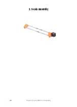
3. X-axis assembly
38
Original Prusa i3 MK3S+ kit assembly
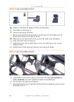
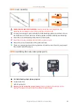
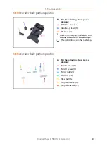
STEP 3
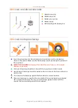
X-axis: x-end idler and motor holder
M3x30 screw (1x)
M3x18 screw (1x)
M3nN nyloc nut (1x)
M3nS nut (1x)
623h bearing with housing (1x)
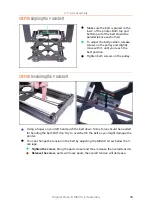
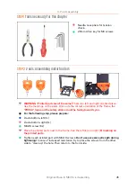
STEP 4
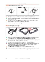
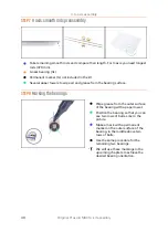
X-axis: inserting linear bearings
Insert linear bearings into the printed parts (X-end-motor and X-end-idler) as
shown in the picture. Make sure the first bearing in each printed part is pushed all
the way down.
DON'T TRY TO PUSH
the bearings from the other side. There is a rim (smaller
diameter of the hole).
First pair of bearings should be in line with the top surface on both X-ends.
Second pair of bearings should be seated on the rim (close to the lower surface) on
both X-ends.
You can press the bearings against the flat surface for easier insertion.
Place two bearings in a way that the inner balls of the second bearing are rotated
45° compared to the first. This way you will achieve greater contact with the
smooth rod. See the third picture for more details.
Summary of Contents for i3 MK3S+
Page 6: ...6 ...
Page 7: ...Original Prusa i3 MK3S kit assembly 7 1 Introduction ...
Page 15: ...Original Prusa i3 MK3S kit assembly 15 2 Y axis assembly ...
Page 36: ...36 Original Prusa i3 MK3S kit assembly 3 X axis assembly ...
Page 44: ...44 Original Prusa i3 MK3S kit assembly 4 Z axis assembly ...
Page 51: ...Original Prusa i3 MK3S kit assembly 51 5 E axis assembly ...
Page 88: ...88 Original Prusa i3 MK3S kit assembly 6 LCD assembly ...
Page 94: ...94 Original Prusa i3 MK3S kit assembly 7 Heatbed PSU assembly ...
Page 108: ...108 Original Prusa i3 MK3S kit assembly 8 Electronics assembly ...
Page 132: ...132 Original Prusa i3 MK3S kit assembly 9 Preflight check ...
Page 137: ...137 Notes ...
Page 138: ...138 ...
Page 139: ...139 Notes ...
Page 140: ...140 ...
Page 141: ...141 Notes ...
Page 142: ...142 ...
Page 143: ...143 Notes ...
Page 144: ...144 ...

