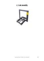
2. Y-axis assembly
Original Prusa i3 MK3S+ kit assembly
19
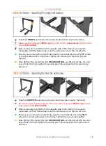
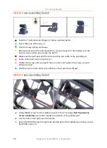
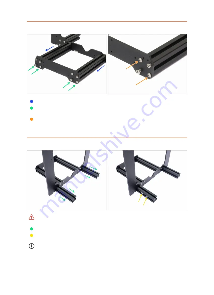
STEP 7
Y-axis: front plate assembly
Rotate the frame with longer extrusions towards you.
Place the front plate on the extrusions and secure it with M5x16r screws,
DON'T
TIGHTEN
them yet!
Now, tighten the screws fully, but
ON A DIAGONAL
, see the second picture. As
soon as you finish the first, tighten the second pair. Then proceed to the second
long extrusion.
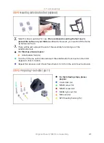
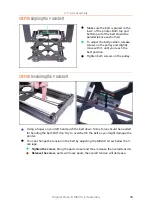
STEP 8
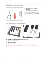
Y-axis: preparation for the PSU
THIS IS A VERY IMPORTANT STEP!
Incorrect placement of PSU holders will lead
to issues later.
Take the YZ frame and rotate it with the shorter extrusions towards you.
Place the PSU holders (M3nE) in the extrusion,
use the side section
, ensure it is the
correct extrusion. See the picture.
The exact spacing of the PSU holders doesn't matter, we will adjust them later.
Summary of Contents for i3 MK3S+
Page 6: ...6 ...
Page 7: ...Original Prusa i3 MK3S kit assembly 7 1 Introduction ...
Page 15: ...Original Prusa i3 MK3S kit assembly 15 2 Y axis assembly ...
Page 36: ...36 Original Prusa i3 MK3S kit assembly 3 X axis assembly ...
Page 44: ...44 Original Prusa i3 MK3S kit assembly 4 Z axis assembly ...
Page 51: ...Original Prusa i3 MK3S kit assembly 51 5 E axis assembly ...
Page 88: ...88 Original Prusa i3 MK3S kit assembly 6 LCD assembly ...
Page 94: ...94 Original Prusa i3 MK3S kit assembly 7 Heatbed PSU assembly ...
Page 108: ...108 Original Prusa i3 MK3S kit assembly 8 Electronics assembly ...
Page 132: ...132 Original Prusa i3 MK3S kit assembly 9 Preflight check ...
Page 137: ...137 Notes ...
Page 138: ...138 ...
Page 139: ...139 Notes ...
Page 140: ...140 ...
Page 141: ...141 Notes ...
Page 142: ...142 ...
Page 143: ...143 Notes ...
Page 144: ...144 ...

