


5. E-axis assembly
Original Prusa i3 MK3S+ kit assembly
55
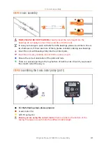
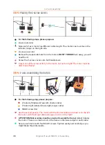
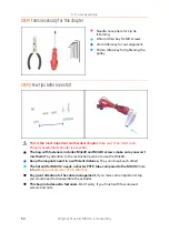
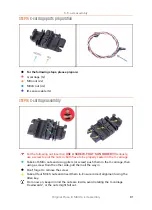
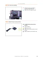
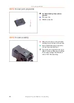
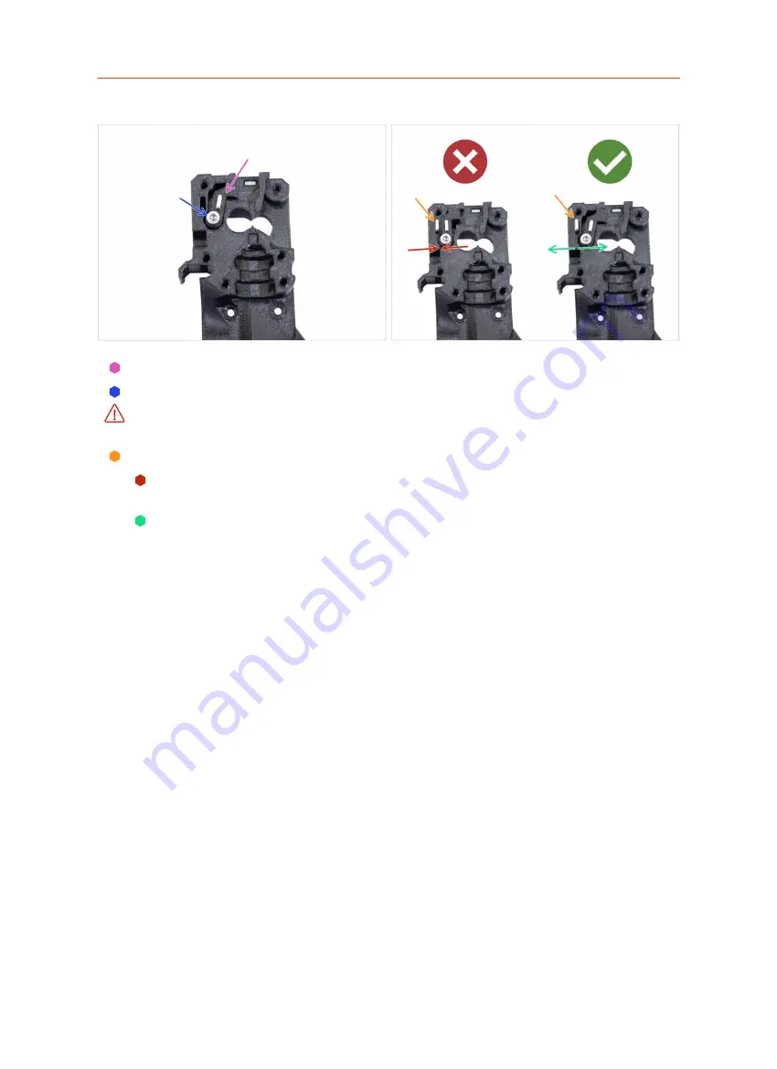
STEP 6
FS-lever assembly
Insert the FS-lever in the body.
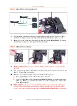
Secure the part with a M3x18. Tighten it, but ensure the lever can move freely.
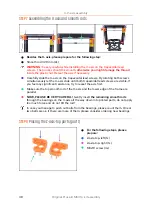
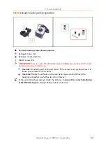
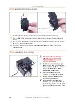
WARNING:
make sure the following procedure is done right, otherwise the
filament sensor won't work!!!
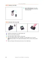
Insert the bigger magnet (20x6x2) in the Extruder-body, it will stick out:
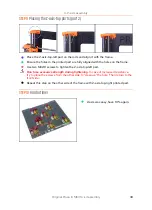
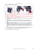
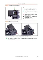
Incorrect setup:
magnets are attracting each other, thus the
lever is pulled to
the left
.
Correct setup:
magnets are repelling each other, thus the
lever is pushed to
the right
.
Summary of Contents for i3 MK3S+
Page 6: ...6 ...
Page 7: ...Original Prusa i3 MK3S kit assembly 7 1 Introduction ...
Page 15: ...Original Prusa i3 MK3S kit assembly 15 2 Y axis assembly ...
Page 36: ...36 Original Prusa i3 MK3S kit assembly 3 X axis assembly ...
Page 44: ...44 Original Prusa i3 MK3S kit assembly 4 Z axis assembly ...
Page 51: ...Original Prusa i3 MK3S kit assembly 51 5 E axis assembly ...
Page 88: ...88 Original Prusa i3 MK3S kit assembly 6 LCD assembly ...
Page 94: ...94 Original Prusa i3 MK3S kit assembly 7 Heatbed PSU assembly ...
Page 108: ...108 Original Prusa i3 MK3S kit assembly 8 Electronics assembly ...
Page 132: ...132 Original Prusa i3 MK3S kit assembly 9 Preflight check ...
Page 137: ...137 Notes ...
Page 138: ...138 ...
Page 139: ...139 Notes ...
Page 140: ...140 ...
Page 141: ...141 Notes ...
Page 142: ...142 ...
Page 143: ...143 Notes ...
Page 144: ...144 ...