


5. E-axis assembly
76
Original Prusa i3 MK3S+ kit assembly
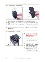
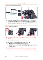
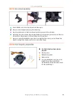
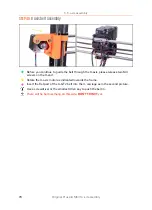
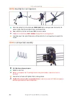
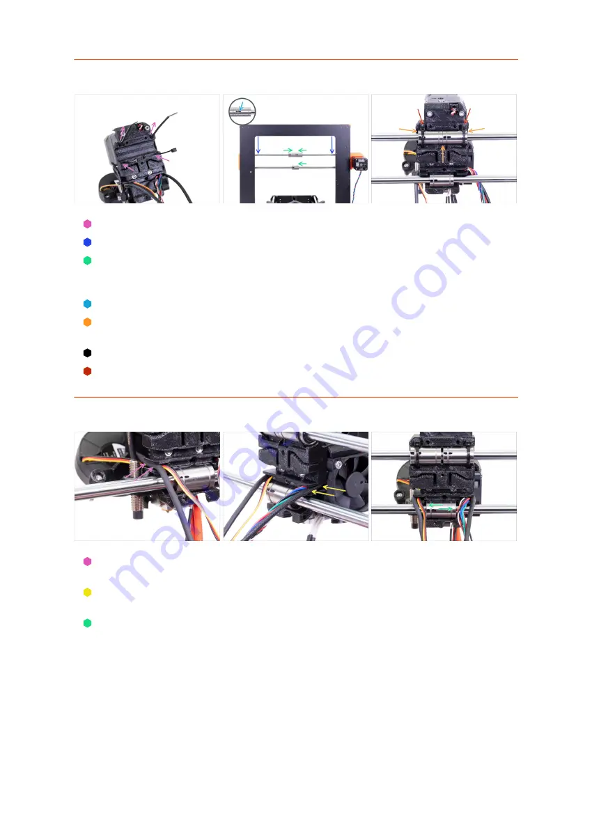
STEP 44
Extruder preparation and mounting
Insert the zip ties in the X-carriage like in the picture.
Lower the X-axis at about 1/3 from the top.
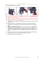
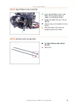
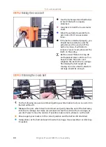
Turn the printer like in the picture with X-axis motor and shorter extrusions facing
towards you. Align the bearings similarly to the picture. The exact position of the
lower bearing doesn't matter for now.
Turn all three bearings so that the markings are facing you.
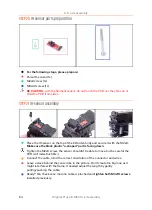
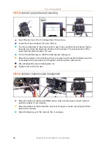
Place the extruder on the bearings, the top couple must fit perfectly. Make sure the
X-carriage is facing towards you (together with the shorter extrusions).
We will adjust the lower bearing later on.
Tighten and cut the zip ties.
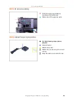
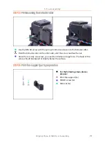
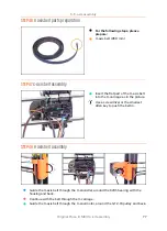
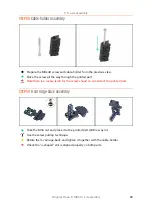
STEP 45
Extruder channels cable management
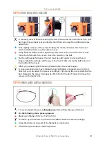
Place the cables on the SuperPINDA sensor side over the lower smooth rod and
push them back in the channel.
Place the cables on the hotend fan side over the lower smooth rod and push them
back in the channel.
Align the bearing, so it fits nicely in the X-carriage.
Summary of Contents for i3 MK3S+
Page 6: ...6 ...
Page 7: ...Original Prusa i3 MK3S kit assembly 7 1 Introduction ...
Page 15: ...Original Prusa i3 MK3S kit assembly 15 2 Y axis assembly ...
Page 36: ...36 Original Prusa i3 MK3S kit assembly 3 X axis assembly ...
Page 44: ...44 Original Prusa i3 MK3S kit assembly 4 Z axis assembly ...
Page 51: ...Original Prusa i3 MK3S kit assembly 51 5 E axis assembly ...
Page 88: ...88 Original Prusa i3 MK3S kit assembly 6 LCD assembly ...
Page 94: ...94 Original Prusa i3 MK3S kit assembly 7 Heatbed PSU assembly ...
Page 108: ...108 Original Prusa i3 MK3S kit assembly 8 Electronics assembly ...
Page 132: ...132 Original Prusa i3 MK3S kit assembly 9 Preflight check ...
Page 137: ...137 Notes ...
Page 138: ...138 ...
Page 139: ...139 Notes ...
Page 140: ...140 ...
Page 141: ...141 Notes ...
Page 142: ...142 ...
Page 143: ...143 Notes ...
Page 144: ...144 ...