3. X-axis assembly
Original Prusa i3 MK3S+ kit assembly
39
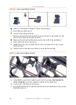
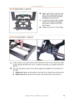
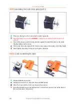
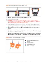
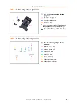
STEP 5
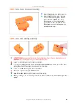
X-end-motor: tensioner assembly
Insert the square nut all the way in.
Insert the M3x30 screw. For now,
we need the screw just to hold in
place. Do not tighten the screw
fully. Leave a 2 mm (0.079 inch)
gap between the screw head and
the plastic part. We will adjust the
final position later.
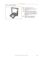
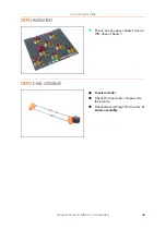
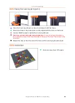
STEP 6
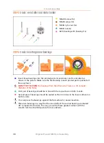
X-end-idler: bearing assembly
ATTENTION
: be very careful during the tightening, check the nut orientation and
DO NOT
use excessive force, you can break this part.
Insert the M3nN nyloc nut in the X-end-idler.
In case you can't press the nut in,
don't use excessive force
. Leave the nut for now
and proceed with the other components for this step.
Insert the 623h bearing into the X-end idler.
Secure it in place using an M3x18 screw.
Now, if needed, use the M3 screw to pull the nut in.
Place your finger on the bearing and ensure it can rotate freely. If needed adjust the
screw.
Summary of Contents for i3 MK3S+
Page 6: ...6 ...
Page 7: ...Original Prusa i3 MK3S kit assembly 7 1 Introduction ...
Page 15: ...Original Prusa i3 MK3S kit assembly 15 2 Y axis assembly ...
Page 36: ...36 Original Prusa i3 MK3S kit assembly 3 X axis assembly ...
Page 44: ...44 Original Prusa i3 MK3S kit assembly 4 Z axis assembly ...
Page 51: ...Original Prusa i3 MK3S kit assembly 51 5 E axis assembly ...
Page 88: ...88 Original Prusa i3 MK3S kit assembly 6 LCD assembly ...
Page 94: ...94 Original Prusa i3 MK3S kit assembly 7 Heatbed PSU assembly ...
Page 108: ...108 Original Prusa i3 MK3S kit assembly 8 Electronics assembly ...
Page 132: ...132 Original Prusa i3 MK3S kit assembly 9 Preflight check ...
Page 137: ...137 Notes ...
Page 138: ...138 ...
Page 139: ...139 Notes ...
Page 140: ...140 ...
Page 141: ...141 Notes ...
Page 142: ...142 ...
Page 143: ...143 Notes ...
Page 144: ...144 ...


