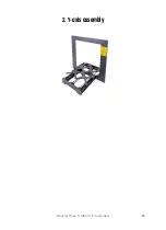


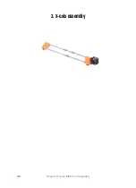


2. Y-axis assembly
Original Prusa i3 MK3S+ kit assembly
29
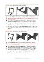
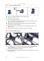
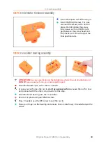
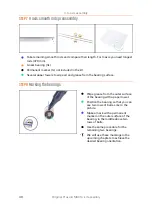
STEP 27
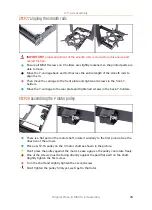
Aligning the smooth rods
IMPORTANT:
proper alignment of the smooth rods is crucial to reduce noise and
overall friction.
Ensure all M3x10 screws on Y-holders are slightly loosened, so the printed parts are
able to move.
Move the Y-carriage back and forth across the entire length of the smooth rods to
align them.
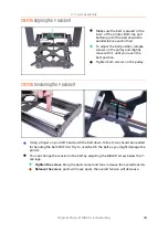
Then move the carriage to the front plate and tighten all screws in the front-Y-
holders.
Move the Y-carriage to the rear plate and tighten all screws in the back-Y-holders.
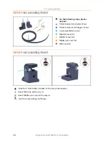
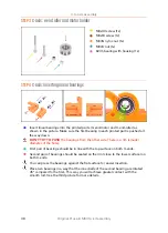
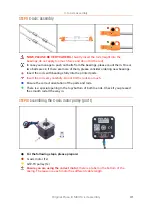
STEP 28
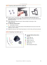
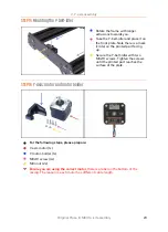
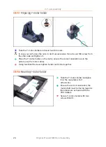
Assembling the Y-motor pulley
There is a flat part on the motor shaft, rotate it similarly to the first picture. See the
direction of the arrows.
Place a GT2-16 pulley on the Y-motor shaft as shown in the picture.
Don't press the pulley against the motor. Leave a gap so the pulley can rotate freely.
One of the screws must be facing directly against the pad (flat part) on the shaft.
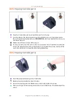
Slightly tighten the first screw.
Turn the shaft and slightly tighten the second screw.
Don't tighten the pulley firmly yet, we'll get to that later.
Summary of Contents for i3 MK3S+
Page 6: ...6 ...
Page 7: ...Original Prusa i3 MK3S kit assembly 7 1 Introduction ...
Page 15: ...Original Prusa i3 MK3S kit assembly 15 2 Y axis assembly ...
Page 36: ...36 Original Prusa i3 MK3S kit assembly 3 X axis assembly ...
Page 44: ...44 Original Prusa i3 MK3S kit assembly 4 Z axis assembly ...
Page 51: ...Original Prusa i3 MK3S kit assembly 51 5 E axis assembly ...
Page 88: ...88 Original Prusa i3 MK3S kit assembly 6 LCD assembly ...
Page 94: ...94 Original Prusa i3 MK3S kit assembly 7 Heatbed PSU assembly ...
Page 108: ...108 Original Prusa i3 MK3S kit assembly 8 Electronics assembly ...
Page 132: ...132 Original Prusa i3 MK3S kit assembly 9 Preflight check ...
Page 137: ...137 Notes ...
Page 138: ...138 ...
Page 139: ...139 Notes ...
Page 140: ...140 ...
Page 141: ...141 Notes ...
Page 142: ...142 ...
Page 143: ...143 Notes ...
Page 144: ...144 ...