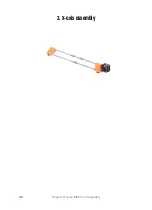
4. Z-axis assembly
46
Original Prusa i3 MK3S+ kit assembly
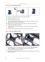
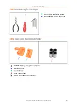
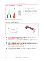
STEP 3
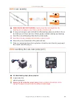
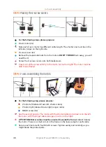
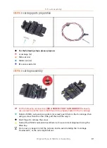
Placing the Z-screw covers
For the following steps, please prepare:
Z-axis motor (2x)
Note each Z-axis motor has different cable length. The shorter one must be on the
left side, longer on the right side.
Z-screw-cover (2x)
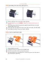
Remove the trapezoidal nuts from the motors.
DON'T THROW
them away, you will
need them!
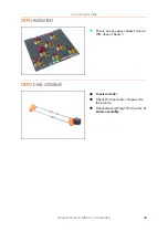
Screw the Z-screw covers onto both leadscrews.
Covers should be screwed fully to the motor, but not too tight! The motor must be
able to spin freely!
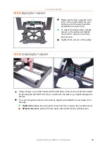
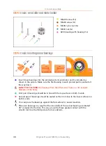
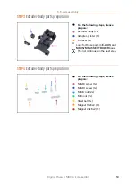
STEP 4
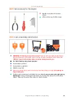
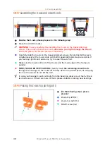
Z-axis: assembling the motors
For the following step, please prepare:
Z motor left (labeled Z axis left, shorter cable)
Z motor right (labeled Z axis right, longer cable)
M3x10 screw (8x)
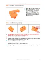
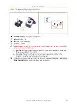
See the second picture. The motor with the shorter cable (red arrow) is on the left,
the motor with the longer cable (orange arrow) is on the right!
ATTENTION: Motor cables must be oriented towards the frame!
Adjust (rotate)
the motor. There is a small cutout in the frame on the lower edge for each cable.
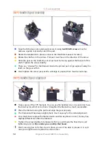
Secure each motor with four M3x10 screws. Tighten evenly and carefully as you
might break the printed parts.
Summary of Contents for i3 MK3S+
Page 6: ...6 ...
Page 7: ...Original Prusa i3 MK3S kit assembly 7 1 Introduction ...
Page 15: ...Original Prusa i3 MK3S kit assembly 15 2 Y axis assembly ...
Page 36: ...36 Original Prusa i3 MK3S kit assembly 3 X axis assembly ...
Page 44: ...44 Original Prusa i3 MK3S kit assembly 4 Z axis assembly ...
Page 51: ...Original Prusa i3 MK3S kit assembly 51 5 E axis assembly ...
Page 88: ...88 Original Prusa i3 MK3S kit assembly 6 LCD assembly ...
Page 94: ...94 Original Prusa i3 MK3S kit assembly 7 Heatbed PSU assembly ...
Page 108: ...108 Original Prusa i3 MK3S kit assembly 8 Electronics assembly ...
Page 132: ...132 Original Prusa i3 MK3S kit assembly 9 Preflight check ...
Page 137: ...137 Notes ...
Page 138: ...138 ...
Page 139: ...139 Notes ...
Page 140: ...140 ...
Page 141: ...141 Notes ...
Page 142: ...142 ...
Page 143: ...143 Notes ...
Page 144: ...144 ...

