


8. Electronics assembly
Original Prusa i3 MK3S+ kit assembly
127
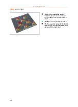
STEP 36
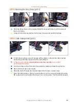
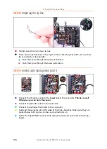
Hotend cable guiding (part 2)
Connect the heatbed thermistor cable (labelled H) to the Einsy board. Leave a slack
on the cable.
Connect the hotend heater cable to the Einsy board. Guide the cable like in the
picture.
Slightly tie the cable bundle with the lower zip tie.
Do not overtighten the zip tie!
Connect the hotend fan cable to the Einsy.
Tie the cable bundle with the upper zip tie. Make sure the hotend fan cable is
included.
Do not overtighten the zip tie!
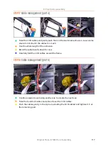
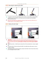
STEP 37
Verify all connections once more!
Check your electronics connection with the first picture.
Compare your cable management with the picture.
Make sure once more the Filament sensor cable is connected to all pins!
Misalignment might lead to permanently damaging the sensor.
Make sure that all connectors are fully inserted and PSU cables properly tightened.
Otherwise, there is a risk of damage to the printer!
Summary of Contents for i3 MK3S+
Page 6: ...6 ...
Page 7: ...Original Prusa i3 MK3S kit assembly 7 1 Introduction ...
Page 15: ...Original Prusa i3 MK3S kit assembly 15 2 Y axis assembly ...
Page 36: ...36 Original Prusa i3 MK3S kit assembly 3 X axis assembly ...
Page 44: ...44 Original Prusa i3 MK3S kit assembly 4 Z axis assembly ...
Page 51: ...Original Prusa i3 MK3S kit assembly 51 5 E axis assembly ...
Page 88: ...88 Original Prusa i3 MK3S kit assembly 6 LCD assembly ...
Page 94: ...94 Original Prusa i3 MK3S kit assembly 7 Heatbed PSU assembly ...
Page 108: ...108 Original Prusa i3 MK3S kit assembly 8 Electronics assembly ...
Page 132: ...132 Original Prusa i3 MK3S kit assembly 9 Preflight check ...
Page 137: ...137 Notes ...
Page 138: ...138 ...
Page 139: ...139 Notes ...
Page 140: ...140 ...
Page 141: ...141 Notes ...
Page 142: ...142 ...
Page 143: ...143 Notes ...
Page 144: ...144 ...