8. Electronics assembly
Original Prusa i3 MK3S+ kit assembly
125
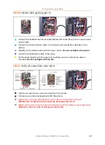
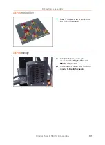
STEP 32
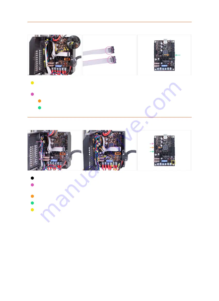
Connecting the LCD cables
Guide both LCD cables like in the picture. Push the cables behind the nylon
filament.
Take the LCD cables and see the marking on both cables.
Connect the LCD cable with
TWO
stripes to the left connector (P2)
Connect the LCD cable with
ONE
stripe to the right connector (P1)
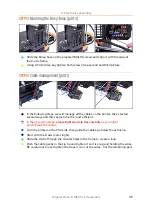
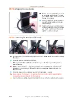
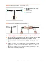
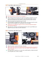
STEP 33
Connecting the motor cables
X-axis motor is already connected.
Connect the Y-axis motor cable (labelled Y) and make a loop with the cable like in
the picture.
Connect both Z-axis motors (labeled Z) and make similar loops with the cables.
Connect the Extruder motor cable (labelled E).
Guide the Power Panic cable like in the picture and plug into the connector in the
right bottom corner.
Summary of Contents for i3 MK3S+
Page 6: ...6 ...
Page 7: ...Original Prusa i3 MK3S kit assembly 7 1 Introduction ...
Page 15: ...Original Prusa i3 MK3S kit assembly 15 2 Y axis assembly ...
Page 36: ...36 Original Prusa i3 MK3S kit assembly 3 X axis assembly ...
Page 44: ...44 Original Prusa i3 MK3S kit assembly 4 Z axis assembly ...
Page 51: ...Original Prusa i3 MK3S kit assembly 51 5 E axis assembly ...
Page 88: ...88 Original Prusa i3 MK3S kit assembly 6 LCD assembly ...
Page 94: ...94 Original Prusa i3 MK3S kit assembly 7 Heatbed PSU assembly ...
Page 108: ...108 Original Prusa i3 MK3S kit assembly 8 Electronics assembly ...
Page 132: ...132 Original Prusa i3 MK3S kit assembly 9 Preflight check ...
Page 137: ...137 Notes ...
Page 138: ...138 ...
Page 139: ...139 Notes ...
Page 140: ...140 ...
Page 141: ...141 Notes ...
Page 142: ...142 ...
Page 143: ...143 Notes ...
Page 144: ...144 ...

