


5. E-axis assembly
84
Original Prusa i3 MK3S+ kit assembly
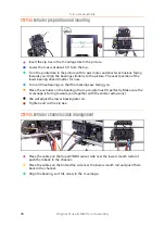
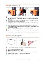
STEP 60
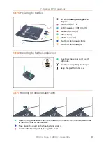
Mounting the X-carriage-back
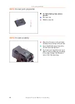
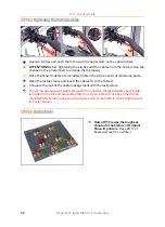
Push the cables from the Extruder
THROUGH
the X-carriage-back. Start with IR-
sensor cable, then the extruder motor and hotend fan.
Next, add the print fan and SuperPINDA sensor cables.
Cables from hotend are
NOT GOING
through the X-carriage-back!
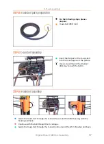
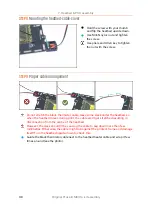
Carefully insert the nylon filament and then slide the X-carriage-back towards the
X-axis.
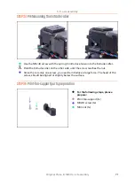
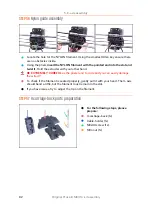
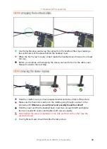
STEP 61
X-carriage-back assembly
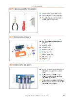
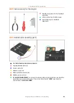
For this step, please prepare:
M3x10 screw (4x)
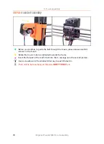
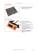
Before you tighten the X-carriage-back, arrange all cables, make sure none is
pinched.
Use all four screws and tighten the X-carriage-back.
Tighten the screws with a reasonable force
, make sure you won't deform/squeeze
the bearings between the printed parts.
Summary of Contents for i3 MK3S+
Page 6: ...6 ...
Page 7: ...Original Prusa i3 MK3S kit assembly 7 1 Introduction ...
Page 15: ...Original Prusa i3 MK3S kit assembly 15 2 Y axis assembly ...
Page 36: ...36 Original Prusa i3 MK3S kit assembly 3 X axis assembly ...
Page 44: ...44 Original Prusa i3 MK3S kit assembly 4 Z axis assembly ...
Page 51: ...Original Prusa i3 MK3S kit assembly 51 5 E axis assembly ...
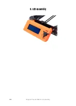
Page 88: ...88 Original Prusa i3 MK3S kit assembly 6 LCD assembly ...
Page 94: ...94 Original Prusa i3 MK3S kit assembly 7 Heatbed PSU assembly ...
Page 108: ...108 Original Prusa i3 MK3S kit assembly 8 Electronics assembly ...
Page 132: ...132 Original Prusa i3 MK3S kit assembly 9 Preflight check ...
Page 137: ...137 Notes ...
Page 138: ...138 ...
Page 139: ...139 Notes ...
Page 140: ...140 ...
Page 141: ...141 Notes ...
Page 142: ...142 ...
Page 143: ...143 Notes ...
Page 144: ...144 ...