


8. Electronics assembly
Original Prusa i3 MK3S+ kit assembly
113
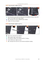
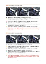
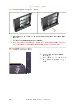
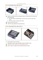
STEP 9
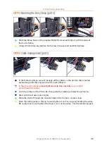
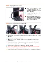
Preparing the Einsy-base (part 2)
Take the four M3nS nuts you've prepared earlier and insert them in the Einsy case
the following way:
Two nuts inside the heatbed holder (note one slot is from the inside of the
cover)
Two nuts inside the extruder cable holder.
Press the nuts all the way in.
Check the proper alignment using an Allen key.
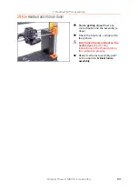
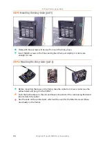
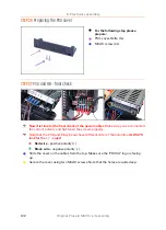
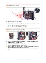
STEP 10
Preparing the Einsy-base (part 3)
Insert four M3n nuts in nut traps.
Slide EINSY inside the base and tighten it with four M3x10 screws.
Tighten the screws carefully, you can damage the board.
Use the needle nose pliers to help with positioning the screws.
Summary of Contents for i3 MK3S+
Page 6: ...6 ...
Page 7: ...Original Prusa i3 MK3S kit assembly 7 1 Introduction ...
Page 15: ...Original Prusa i3 MK3S kit assembly 15 2 Y axis assembly ...
Page 36: ...36 Original Prusa i3 MK3S kit assembly 3 X axis assembly ...
Page 44: ...44 Original Prusa i3 MK3S kit assembly 4 Z axis assembly ...
Page 51: ...Original Prusa i3 MK3S kit assembly 51 5 E axis assembly ...
Page 88: ...88 Original Prusa i3 MK3S kit assembly 6 LCD assembly ...
Page 94: ...94 Original Prusa i3 MK3S kit assembly 7 Heatbed PSU assembly ...
Page 108: ...108 Original Prusa i3 MK3S kit assembly 8 Electronics assembly ...
Page 132: ...132 Original Prusa i3 MK3S kit assembly 9 Preflight check ...
Page 137: ...137 Notes ...
Page 138: ...138 ...
Page 139: ...139 Notes ...
Page 140: ...140 ...
Page 141: ...141 Notes ...
Page 142: ...142 ...
Page 143: ...143 Notes ...
Page 144: ...144 ...