


5. E-axis assembly
62
Original Prusa i3 MK3S+ kit assembly
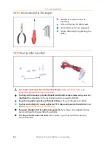
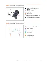
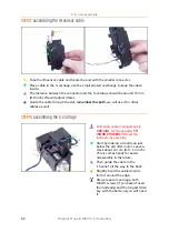
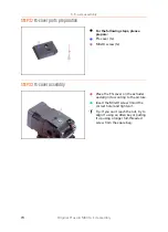
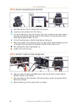
STEP 17
Assembling the IR-sensor cable
Take the IR-sensor cable and locate the end with the smaller connector.
Place cable in the X-carriage, use the small printed overhangs to keep the cable
inside.
The distance between the connector and the X-carriage should be around 15 mm
(0.6 inch). We will adjust it later.
Guide the cable through the slot,
remember this path
, we will use it for other
cables as well.
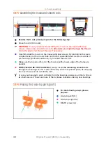
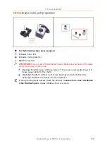
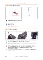
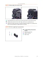
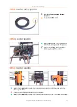
STEP 18
Assembling the X-carriage
Following cable management is
CRUCIAL
for the extruder
TO
WORK PROPERLY!
Read the
instructions carefully.
Start by making a small loop just
below the extruder motor. Leave a
slack about 2-3 cm (0.8 - 1.2 inch).
This is comes handy for easier
disassembly in the future.
Then guide the cable in the
"channel" all the way to the back.
Slightly bend the cable down to
form it around the edge.
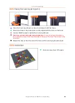
Also, prepare X-carriage, both
M3x10 screws (if you haven't used
them already) and the longest Allen
key with the ball-end, you will need
it.
Summary of Contents for i3 MK3S+
Page 6: ...6 ...
Page 7: ...Original Prusa i3 MK3S kit assembly 7 1 Introduction ...
Page 15: ...Original Prusa i3 MK3S kit assembly 15 2 Y axis assembly ...
Page 36: ...36 Original Prusa i3 MK3S kit assembly 3 X axis assembly ...
Page 44: ...44 Original Prusa i3 MK3S kit assembly 4 Z axis assembly ...
Page 51: ...Original Prusa i3 MK3S kit assembly 51 5 E axis assembly ...
Page 88: ...88 Original Prusa i3 MK3S kit assembly 6 LCD assembly ...
Page 94: ...94 Original Prusa i3 MK3S kit assembly 7 Heatbed PSU assembly ...
Page 108: ...108 Original Prusa i3 MK3S kit assembly 8 Electronics assembly ...
Page 132: ...132 Original Prusa i3 MK3S kit assembly 9 Preflight check ...
Page 137: ...137 Notes ...
Page 138: ...138 ...
Page 139: ...139 Notes ...
Page 140: ...140 ...
Page 141: ...141 Notes ...
Page 142: ...142 ...
Page 143: ...143 Notes ...
Page 144: ...144 ...