8. Electronics assembly
126
Original Prusa i3 MK3S+ kit assembly
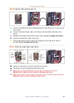
STEP 34
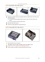
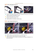
Preparing the zip ties
Slightly bend the tip on two zip ties.
There are two perforations in the right corner of the Einsy base. We will use them
for securing the cable bundle.
Push the zip tie through the upper perforation.
Push the zip tie through the lower perforation.
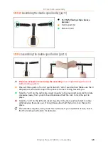
STEP 35
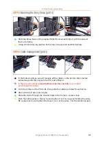
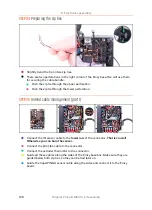
Hotend cable management (part 1)
Connect the IR-sensor cable to the
lower row
of the connector.
That is crucial!
Otherwise you can burn the sensor.
Connect the print fan cable to the connector.
Connect the extruder thermistor to the connector.
Guide all these cables along the sides of the Einsy base box. Make sure they are
guided below both zip ties, so they can be tied later on.
Guide the SuperPINDA sensor cable along the sides and connect it to the Einsy
board.
Summary of Contents for i3 MK3S+
Page 6: ...6 ...
Page 7: ...Original Prusa i3 MK3S kit assembly 7 1 Introduction ...
Page 15: ...Original Prusa i3 MK3S kit assembly 15 2 Y axis assembly ...
Page 36: ...36 Original Prusa i3 MK3S kit assembly 3 X axis assembly ...
Page 44: ...44 Original Prusa i3 MK3S kit assembly 4 Z axis assembly ...
Page 51: ...Original Prusa i3 MK3S kit assembly 51 5 E axis assembly ...
Page 88: ...88 Original Prusa i3 MK3S kit assembly 6 LCD assembly ...
Page 94: ...94 Original Prusa i3 MK3S kit assembly 7 Heatbed PSU assembly ...
Page 108: ...108 Original Prusa i3 MK3S kit assembly 8 Electronics assembly ...
Page 132: ...132 Original Prusa i3 MK3S kit assembly 9 Preflight check ...
Page 137: ...137 Notes ...
Page 138: ...138 ...
Page 139: ...139 Notes ...
Page 140: ...140 ...
Page 141: ...141 Notes ...
Page 142: ...142 ...
Page 143: ...143 Notes ...
Page 144: ...144 ...


