8. Electronics assembly
120
Original Prusa i3 MK3S+ kit assembly
STEP 23
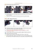
PSU and HB power cables
IMPORTANT
: it is
CRUCIAL
to connect the PSU and HB cables in correct order to
the EINSY board.
POSITIVE WIRE
must be connected to
POSITIVE SLOT
. There
are
TWO VERSIONS
of the cables with different coloring system:
Version A
: both wires on each pair are black,
POSITIVE WIRE
is marked with a
RED LINE
Version B
: on each pair, there is a red and black wire.
POSITIVE WIRE
is
FULLY RED
.
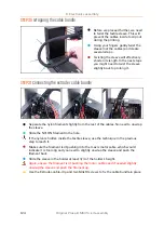
Connect wires from PSU and HEATBED to the EINSY board in the following order
(red arrows indicate positive slot):
The first cable from the PSU (A+|A-).
The second cable from the PSU (B+|B-).
Cable from the heatbed (C+|C-).
Both cables (two pairs) from the PSU are the same, their order doesn't matter, just
ensure correct polarity.
Summary of Contents for i3 MK3S+
Page 6: ...6 ...
Page 7: ...Original Prusa i3 MK3S kit assembly 7 1 Introduction ...
Page 15: ...Original Prusa i3 MK3S kit assembly 15 2 Y axis assembly ...
Page 36: ...36 Original Prusa i3 MK3S kit assembly 3 X axis assembly ...
Page 44: ...44 Original Prusa i3 MK3S kit assembly 4 Z axis assembly ...
Page 51: ...Original Prusa i3 MK3S kit assembly 51 5 E axis assembly ...
Page 88: ...88 Original Prusa i3 MK3S kit assembly 6 LCD assembly ...
Page 94: ...94 Original Prusa i3 MK3S kit assembly 7 Heatbed PSU assembly ...
Page 108: ...108 Original Prusa i3 MK3S kit assembly 8 Electronics assembly ...
Page 132: ...132 Original Prusa i3 MK3S kit assembly 9 Preflight check ...
Page 137: ...137 Notes ...
Page 138: ...138 ...
Page 139: ...139 Notes ...
Page 140: ...140 ...
Page 141: ...141 Notes ...
Page 142: ...142 ...
Page 143: ...143 Notes ...
Page 144: ...144 ...


