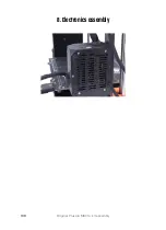
8. Electronics assembly
122
Original Prusa i3 MK3S+ kit assembly
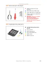
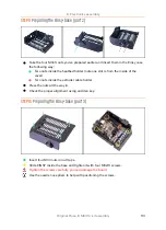
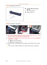
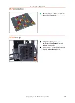
STEP 26
Preparing the PSU cover
For the following step please
prepare:
PSU-cover-Delta (1x)
M3x10 screw (2x)
STEP 27
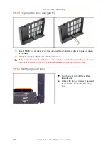
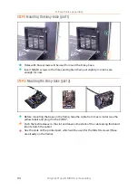
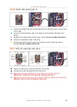
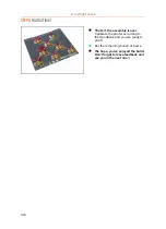
PSU and HB - final check
Now it is time for the final check of the power cables
. Make sure you've connected
the correct polarity and tightened the screws properly.
Note that the PSU and Einsy board have different order of the polarities,
ALWAYS
look for the + / - signs!
Red wire
- positive polarity (+)
Black wire
- negative polarity (-)
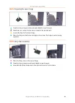
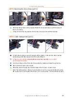
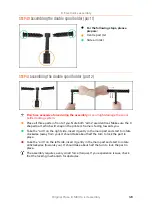
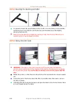
Slide the cover on the cables from the top. Make sure the "PRUSA" logo is facing
up.
Secure the cover using two M3x10 screws. Note that the holes are quite deep.
Summary of Contents for i3 MK3S+
Page 6: ...6 ...
Page 7: ...Original Prusa i3 MK3S kit assembly 7 1 Introduction ...
Page 15: ...Original Prusa i3 MK3S kit assembly 15 2 Y axis assembly ...
Page 36: ...36 Original Prusa i3 MK3S kit assembly 3 X axis assembly ...
Page 44: ...44 Original Prusa i3 MK3S kit assembly 4 Z axis assembly ...
Page 51: ...Original Prusa i3 MK3S kit assembly 51 5 E axis assembly ...
Page 88: ...88 Original Prusa i3 MK3S kit assembly 6 LCD assembly ...
Page 94: ...94 Original Prusa i3 MK3S kit assembly 7 Heatbed PSU assembly ...
Page 108: ...108 Original Prusa i3 MK3S kit assembly 8 Electronics assembly ...
Page 132: ...132 Original Prusa i3 MK3S kit assembly 9 Preflight check ...
Page 137: ...137 Notes ...
Page 138: ...138 ...
Page 139: ...139 Notes ...
Page 140: ...140 ...
Page 141: ...141 Notes ...
Page 142: ...142 ...
Page 143: ...143 Notes ...
Page 144: ...144 ...

