8. Electronics assembly
Original Prusa i3 MK3S+ kit assembly
115
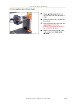
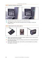
STEP 13
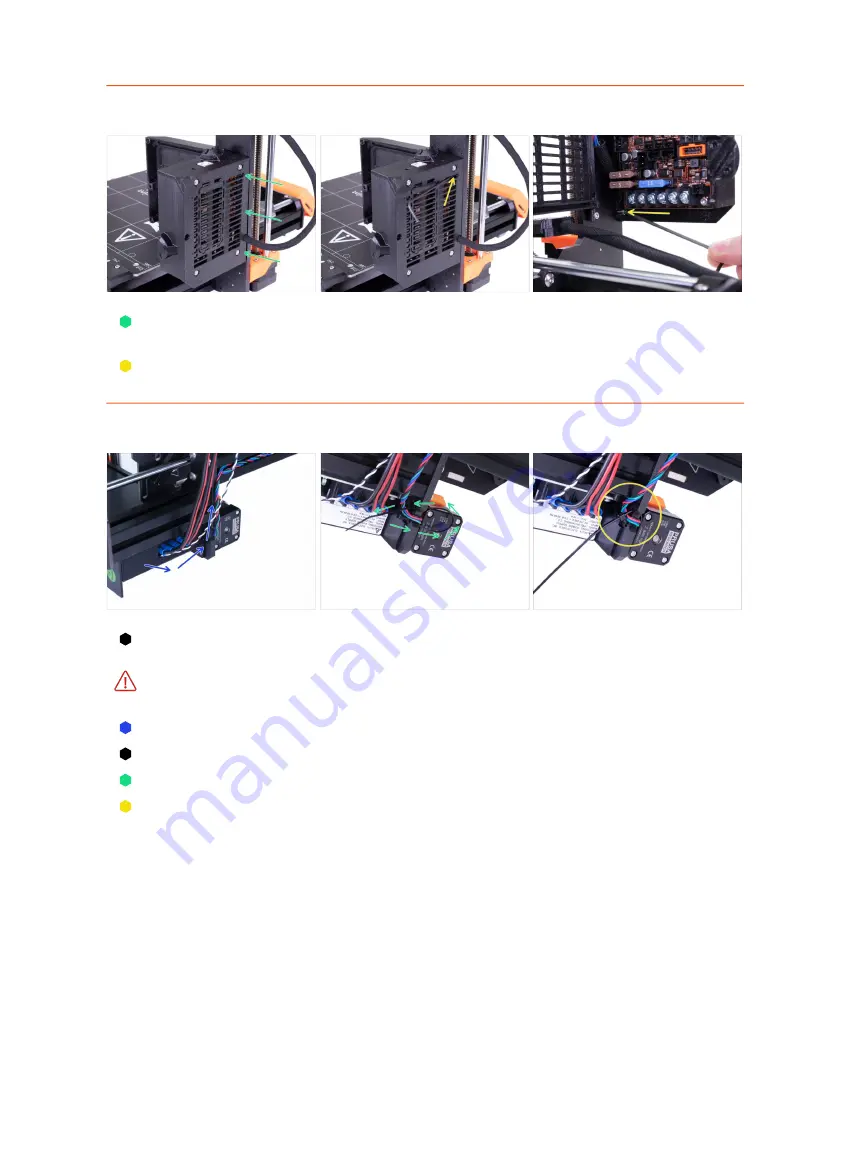
Mounting the Einsy-base (part 3)
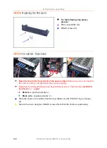
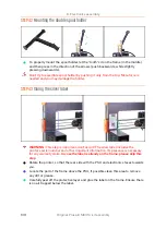
Slide the Einsy-base on the prepared M3x10 screws and align it with the edge of
the Z-axis frame.
Using 2.5mm Allen key tighten both screws. See second and third picture.
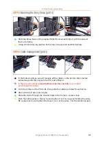
STEP 14
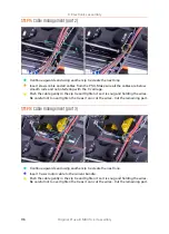
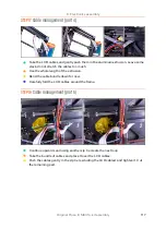
Cable management (part 1)
In the following steps, we will manage all the cables on the printer. We've tested
several ways and this seems to be the most efficient.
In the upcoming steps,
please tighten all zip ties carefully
as you might
pinch/break the cables.
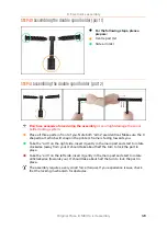
Turn the printer on the PSU side, then guide the cables go below the extrusion.
Start with the Z-axis motor (right).
Slide the zip tie through the circular holes in the frame to create a loop.
Push the cable gently in the zip tie and tighten it so it is snug and holding the wires.
Be careful not to over tighten the tie as it can cut the wires . Cut the remaining part.
Summary of Contents for i3 MK3S+
Page 6: ...6 ...
Page 7: ...Original Prusa i3 MK3S kit assembly 7 1 Introduction ...
Page 15: ...Original Prusa i3 MK3S kit assembly 15 2 Y axis assembly ...
Page 36: ...36 Original Prusa i3 MK3S kit assembly 3 X axis assembly ...
Page 44: ...44 Original Prusa i3 MK3S kit assembly 4 Z axis assembly ...
Page 51: ...Original Prusa i3 MK3S kit assembly 51 5 E axis assembly ...
Page 88: ...88 Original Prusa i3 MK3S kit assembly 6 LCD assembly ...
Page 94: ...94 Original Prusa i3 MK3S kit assembly 7 Heatbed PSU assembly ...
Page 108: ...108 Original Prusa i3 MK3S kit assembly 8 Electronics assembly ...
Page 132: ...132 Original Prusa i3 MK3S kit assembly 9 Preflight check ...
Page 137: ...137 Notes ...
Page 138: ...138 ...
Page 139: ...139 Notes ...
Page 140: ...140 ...
Page 141: ...141 Notes ...
Page 142: ...142 ...
Page 143: ...143 Notes ...
Page 144: ...144 ...

