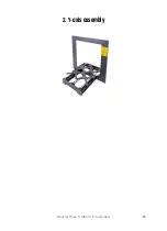
2. Y-axis assembly
Original Prusa i3 MK3S+ kit assembly
23
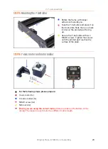
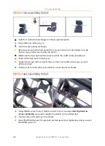
STEP 15
Mounting the Y-belt-idler
Rotate the frame with longer
extrusions towards you.
Take the Y-belt-idler and place it on
the front plate. Note there is a mark
(circle) on the printed part facing
up.
Secure the Y-belt-idler with two
M3x10 screws. Tighten the screws
until the printed part reaches the
surface of the plate.
STEP 16
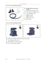
Y-axis: motor and motor holder
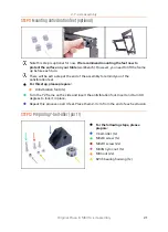
For the following steps, please prepare:
Y-axis motor (1x)
Y-motor-holder (1x)
M3x10 screw (4x)
M3n nut (2x)
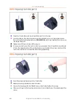
Ensure you are using the correct motor
, there is a label on the bottom of the
casing. The reason is, each motor has different cable length.
Summary of Contents for i3 MK3S+
Page 6: ...6 ...
Page 7: ...Original Prusa i3 MK3S kit assembly 7 1 Introduction ...
Page 15: ...Original Prusa i3 MK3S kit assembly 15 2 Y axis assembly ...
Page 36: ...36 Original Prusa i3 MK3S kit assembly 3 X axis assembly ...
Page 44: ...44 Original Prusa i3 MK3S kit assembly 4 Z axis assembly ...
Page 51: ...Original Prusa i3 MK3S kit assembly 51 5 E axis assembly ...
Page 88: ...88 Original Prusa i3 MK3S kit assembly 6 LCD assembly ...
Page 94: ...94 Original Prusa i3 MK3S kit assembly 7 Heatbed PSU assembly ...
Page 108: ...108 Original Prusa i3 MK3S kit assembly 8 Electronics assembly ...
Page 132: ...132 Original Prusa i3 MK3S kit assembly 9 Preflight check ...
Page 137: ...137 Notes ...
Page 138: ...138 ...
Page 139: ...139 Notes ...
Page 140: ...140 ...
Page 141: ...141 Notes ...
Page 142: ...142 ...
Page 143: ...143 Notes ...
Page 144: ...144 ...


