4. Z-axis assembly
Original Prusa i3 MK3S+ kit assembly
49
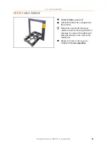
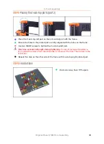
STEP 9
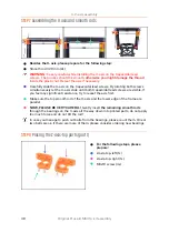
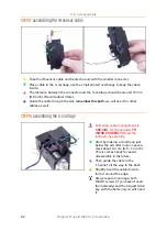
Placing the Z-axis-top parts (part 2)
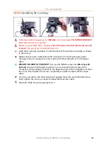
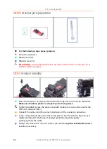
Place the Z-axis-top-left part on the rods and align it with the frame.
Ensure the holes in the printed part are fully aligned with the holes on the frame.
Use two M3x10 screws to tighten the Z-axis-top-left part.
Don't use excessive strength during tightening.
In case of increased resistance,
try to place the screws from the other side to "clean up" the hole. Then return to the
front side.
Repeat this step on the other side of the frame with Z-axis-top-right printed part.
STEP 10
Haribo time!
Z-axis was easy, have 10 % again.
Summary of Contents for i3 MK3S+
Page 6: ...6 ...
Page 7: ...Original Prusa i3 MK3S kit assembly 7 1 Introduction ...
Page 15: ...Original Prusa i3 MK3S kit assembly 15 2 Y axis assembly ...
Page 36: ...36 Original Prusa i3 MK3S kit assembly 3 X axis assembly ...
Page 44: ...44 Original Prusa i3 MK3S kit assembly 4 Z axis assembly ...
Page 51: ...Original Prusa i3 MK3S kit assembly 51 5 E axis assembly ...
Page 88: ...88 Original Prusa i3 MK3S kit assembly 6 LCD assembly ...
Page 94: ...94 Original Prusa i3 MK3S kit assembly 7 Heatbed PSU assembly ...
Page 108: ...108 Original Prusa i3 MK3S kit assembly 8 Electronics assembly ...
Page 132: ...132 Original Prusa i3 MK3S kit assembly 9 Preflight check ...
Page 137: ...137 Notes ...
Page 138: ...138 ...
Page 139: ...139 Notes ...
Page 140: ...140 ...
Page 141: ...141 Notes ...
Page 142: ...142 ...
Page 143: ...143 Notes ...
Page 144: ...144 ...

